Difference between revisions of "Assembly Tutorial"
| Line 29: | Line 29: | ||
:Notice how the truck in the picture is setup with the same orientation. | :Notice how the truck in the picture is setup with the same orientation. | ||
| − | [[File:W6.JPG]][[File:W7.PNG]] | + | [[File:W6.JPG|20px]][[File:W7.PNG]] |
Revision as of 06:48, 3 July 2014
Before you Begin
This tutorial is designed to step you through creating an assembly. As you go through this tutorial, later procedures will assume that you understand all earlier procedures. Because of this, it is very important that you carefully step through this guide, understanding everything along the way and following all steps in order.
We would like to cover a few key items before starting the step-by-step instructions of the tutorial. It is very important you completely understand these items:
- 1) PickPoints
- PICKPOINTS ARE USED FOR EVERYTHING. The assembly part of the software is largely run in full 3D. Because a computer screen is only 2D, there is an unlimited amount of depth behind and in front of the cursor. A PickPoint is a point in 3D space that can be used for creating, editing, and placing parts in assembly. PickPoints can be placed in a 2D environment by having their depth manually entered.
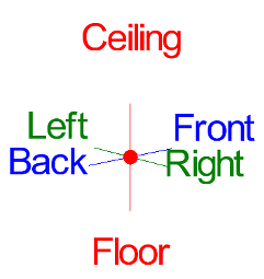
- There are 2 types of PickPoints; Automatically created by the part (various colors) and user-defined points (green). In addition our (0,0,0) point is an automatic point that resides at the center of the Tri-Star. The Tri-Star is our directional definition locator.
- 2) Center Line & Apex
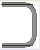
- Center Line: In the assembly environment we are working exclusively with the center-line of a part, as compared to the inside or outside.
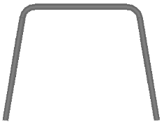
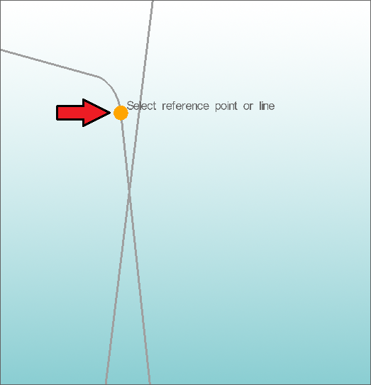
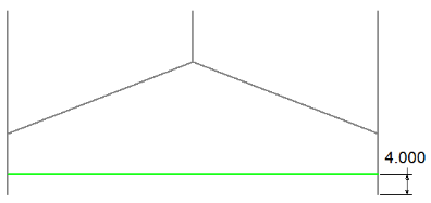
- Apex: The bend locations are created in assembly exclusively with the apex. Our definition of apex is the intersection of the straight tubes as if there wasn’t a radius.
- This is demonstrated in the picture below.
- 3) Defining Parts
- It is possible to create parts in the template and custom part interfaces, however, starting out this way tends to get confusing for new users of the software. It appears that there is a higher level of success with customers who start out designing parts directly in the assembly interface.
- 4) Sense of Direction
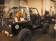
- It seams to work the best if users think as if they are standing behind the vehicle. This way left is left and right is right. Take a minute and examine the Tri-Star to get your orientation.
- Notice how the truck in the picture is setup with the same orientation.
Assembly Tutorial
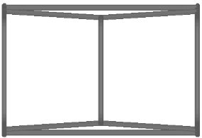
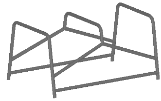
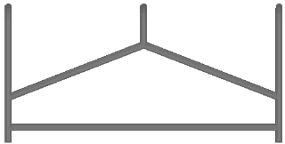
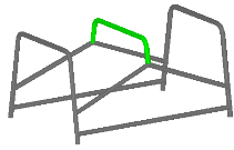
In this tutorial we will be building the assembly as shown in the pictures below:
Start out by selecting the File -> New -> Assembly from the main pull-down menu at the top of the screen. Alternatively, you may also click the New Assembly icon in the main toolbar.
The Assembly window is broke down into 3 main areas. On the left is the tab area where we make our feature selections and value inputs. On the right is the graphical area where we make our screen selections and can visually see our assembly. Along the top is a set of the most common functions you will most-likely use within the assembly.
Creating the 1st Part:
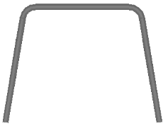
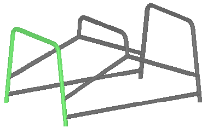
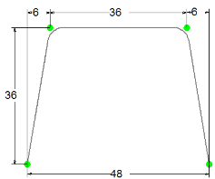
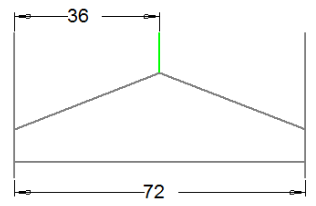
Notice we have highlighted the part we are going to work on first. The dimensions for this part are displayed in the picture below.We are going to create the 4 PickPoints representing this part.
Select the PickPoints Tab.
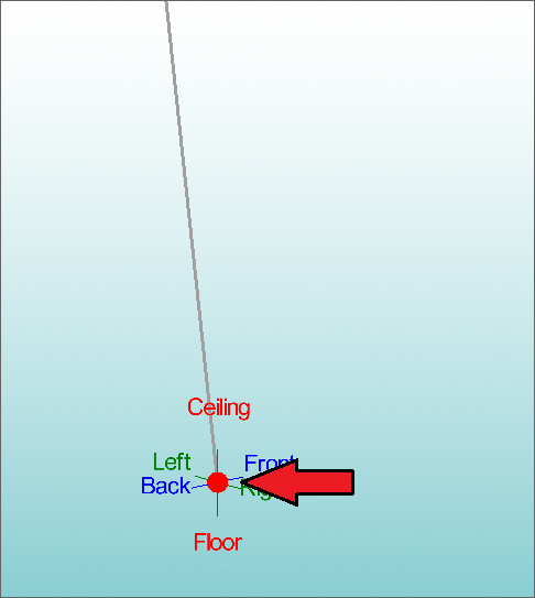
Click the Set Reference button and then pick the point at the center of the Tri-Star. It maybe hard to see, however, there is a green PickPoint at the center. When the PickPoint is selected it should turn RED or PURPLE.
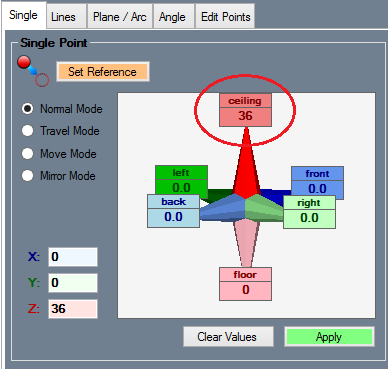
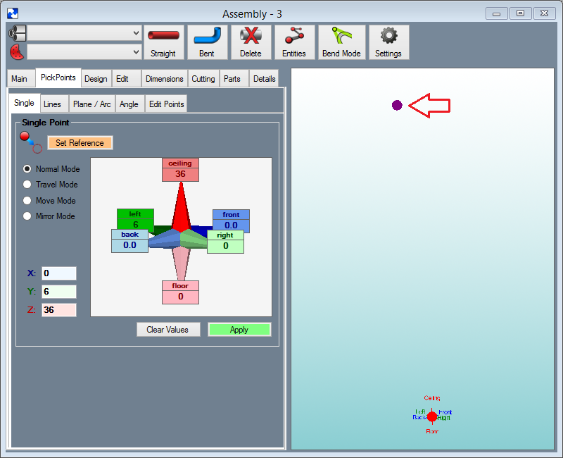
Enter a value of 36 into the Ceiling field.
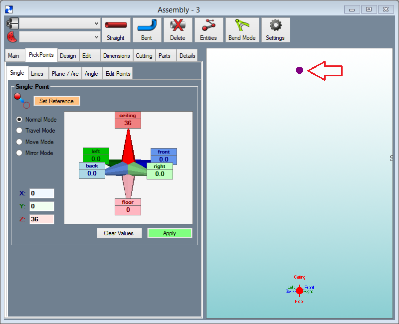
You will notice a purple PickPoint now located straight up from our Tri-Star point. This new point represents 36 to Ceiling from our selected reference point, which in this case is our Tri-Star location.
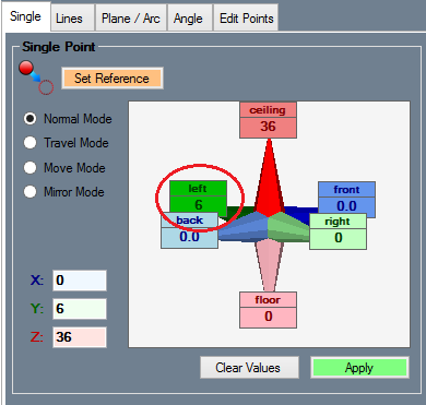
If we take a careful look at our part design, you will notice the bend locations are not straight up, but are placed 6 inches inward.
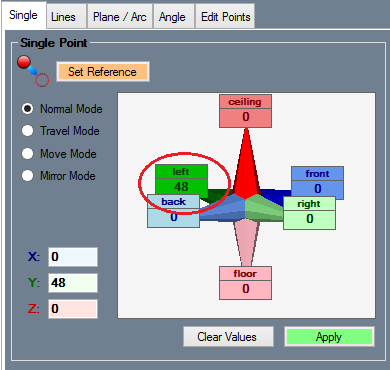
Enter 6 into the Left field.
Press the Apply button. This will turn the new PickPoint from a purple dot to a green dot. Now click the Clear Values button to clear the fields. Your display window should look similar to the picture below, with a PickPoint at the center of the Tri-Star and a new point above and slightly to the left of the Tri-Star.
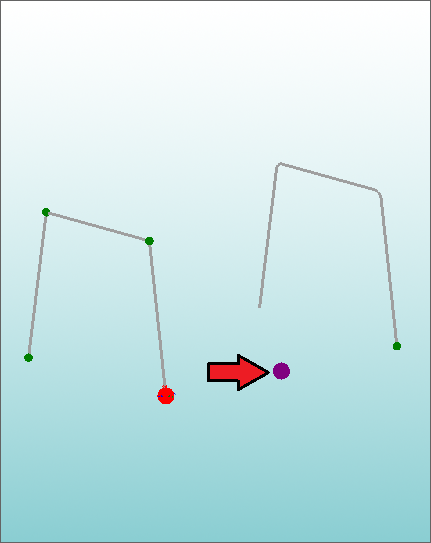
Select your new PickPoint so that it becomes our Reference Point. Now this point should turn RED or PURPLE.
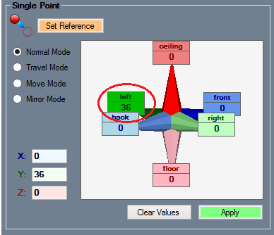
Enter 36 in the Left field. Notice the PURPLE PickPoint up and to the left from your reference point. This is shown in the picture below. WARNING: Make sure the other 5 fields have only zero or are blank.
Select the Apply button.
Select the PickPoint at the center of the Tri-Star as your reference point.
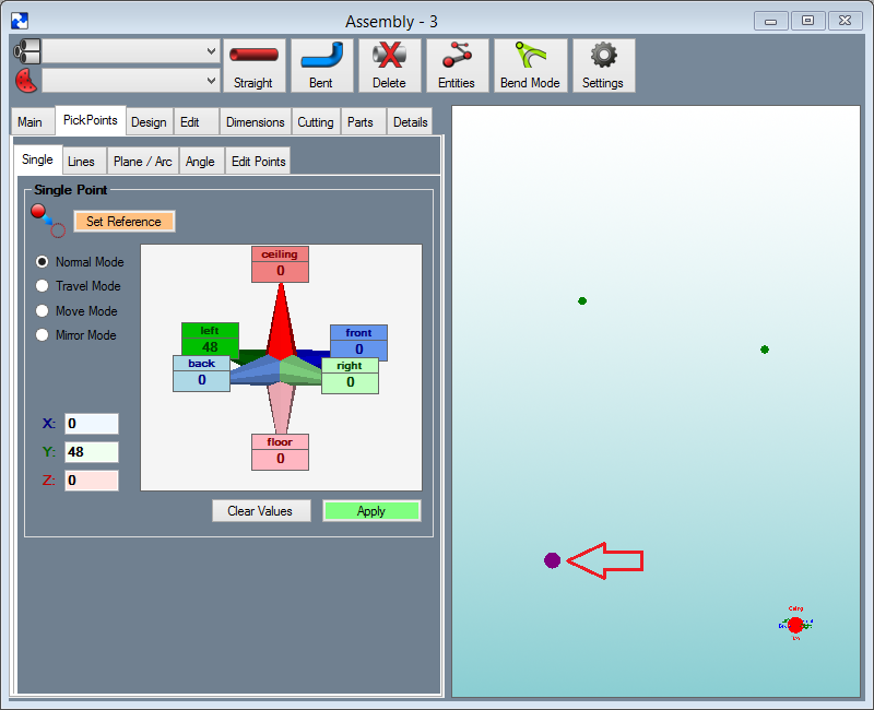
Enter 48 into the Left field. Again make sure the other 5 fields have only zero. Notice the PURPLE PickPoint displayed as shown in the picture below.
In order to start creating parts, we need to have a die and material defined. For this tutorial, we will create an example die and material to use.
Go to the Tools menu on the main menu bar at the very top of the screen and select Die Library.
Click the Add New' button. Type 2.0 in the Die Name field, 2 in the Achieved CLR field, 2 in the Calibrated CLR field, and 0 in the Bend Location Offset field.
For more information on these values and what they mean, please refer to the Die Library section.
Next click the Save button to save this die. Now close the Die Library by selecting the Close button.
Go to the Tools menu on the main menu bar again and select Tube / Pipe Library. Click the Add New button. Enter 1.0 in the Material Name field. Enter 1 in the Diameter field and 0.125 in the Wall Thickness field. Click the Save button and then click the Close button.
Back in the assembly, we will select the new die and material we just added. From the Die drop-down list in the upper-left corner, select the 2.0 die. In the Material drop-down list, select the 1.0 material.
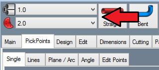
We will now create our first bent part. Select the Bent button at the top of the assembly.
Now we are asked for the Number of Bends. As you can see from our diagram on the right, the part consists of 2 bends. In the Number of Bends dialog box, clear the field and enter 2.
File:W29.PNGClick the OK button to accept the number of bends and close the dialog.
Now we are going to use the cursor to select the PickPoints for the part. When you are selecting the PickPoints for a bent part, you must select the first end of the part, the apex of each bend in order, and the the other end of the part. To start this part, click the point at the center of the Tri-Star.
The PickPoint that you select will turn red and a line will be drawn between it and your cursor. Both of these things are indications that you have successfully selected the PickPoint.
Click the top right point, followed by the top left point, followed by the bottom left point.
After the last selection the Part Name dialog will appear. The first part that is created has a default name of Part 1. You can change the part name if you desire, however, we will be referring to this part as Part 1 through out the rest of this tutorial.
Select the OK button to accept the name and continue.
Notice how the part changes. The apex points we used are now changed to arcs. These points represent the apex of each bend. The apex is defined as the intersection of each leg on either side of the bend. Where the two legs intersect is the apex. Because of this, it is important to understand the needed location when defining bends.
You will now find our new part as a item in our Master Part List located under the Main Tab. The Master Part List is where the parts we have used (or ones we want to use) are stored. This is NOT a list of the parts in our assembly, it is simply a list of parts that are available to be used in the current assembly project.
It is now time to create our second part. This part is exactly the same as the first part. We are going to create one more PickPoint and then paste the part at that location.
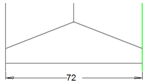
The distance from our first part to our second part is 72 inches (shown below) Note that this distance is from center to center.
We will first create the new PickPoint 72 inches towards the front.
Select the PickPoints Tab and make sure the Single Tab is selected.
Select the Set Reference button.
Once again, we will use the Tri-Star point as our reference. Select the Tri-Star point (the point should turn RED or PURPLE).
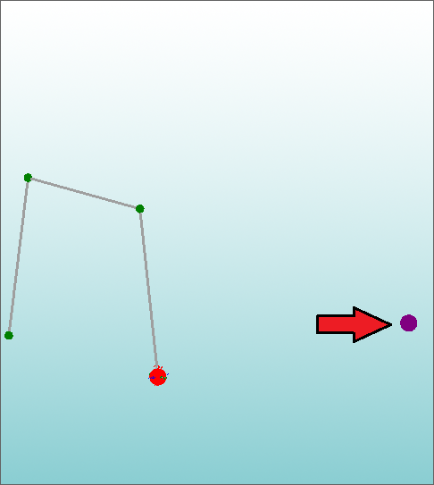
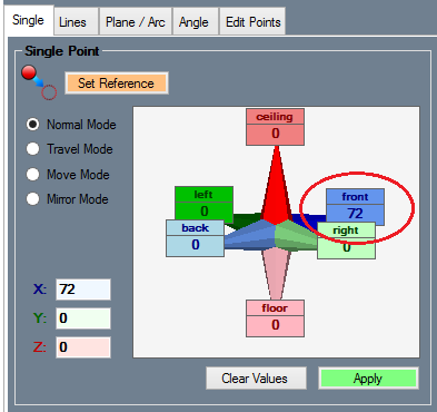
Enter 72 into the Front field. You will find a new PURPLE PickPoint in your assembly as seen in the picture below.
Select the Apply command button to create the new point.
Now we are going to Paste the first part we created onto this new point. Select the Main Tab and then select Part 1 from the Master Part List.
Now select the Paste command button.
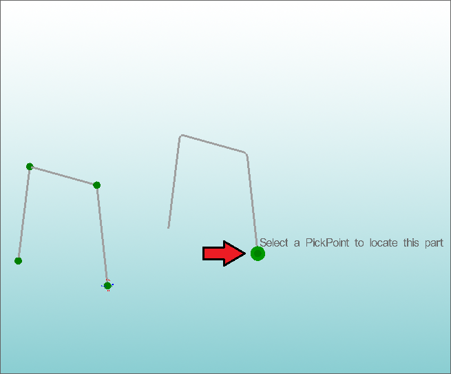
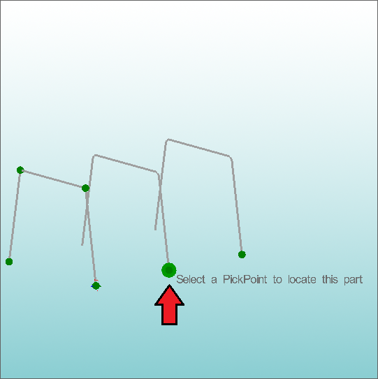
As you move the cursor over your assembly you will find a copy of 111Part 1 attached to your cursor. Help text will also be displayed, prompting you to Select a PickPoint to locate this part (shown below). Select our newest PickPoint to paste the part.
Our third part is like our first two parts, except it has shorter legs. We will first paste the same part again, then we can shorten the legs.
As shown, the part is 36 inches to the front from our first part (again, this distance is center to center).
As shown below, this part will have its legs shortened.
Select the PickPoints Tab.
Select the 'Set Reference button.
Select the Tri-Star point and then enter 36 into the Front field.
Select the Apply button.
Once again, we are going to Paste the part onto this new PickPoint. Select the Main Tab and then select Part 1 from the Master Parts List.
Now select the Paste command button.
Your assembly project should now look like the picture below. We have created three identical parts in the assembly.
Now we need to adjust our center part (shorten the legs). As you can see we know the straight sections of the part need to be 7 inches. The process we will use will be to place 2 additional PickPoints and then move each end of the part to the new location.
We are going to learn about a new technique, PickPoint Line, to place a PickPoint. This function allows you to define a line and then place a new PickPoint anywhere on that line by entering the distance from the first end of the line.
Select the PickPoints Tab.
Select the Lines Tab.
Now select the Set Reference button under the Line (Two Points) section (the top button).
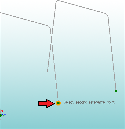
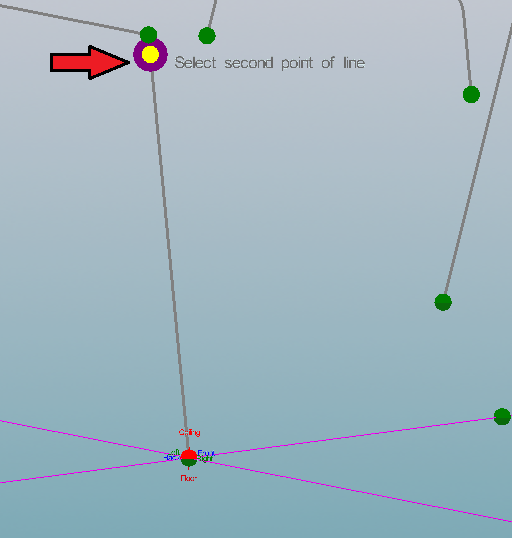
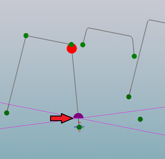
Hover over the start point of the arc on the third (center) part and you should notice a point appear. Click on this point and you should then notice a line attached to this point and your cursor. You may need to move your cursor away from the part in order to see the line. Refer to the picture below for help on which point you should click.
Now click on the point that you used to place the third part. See the picture below to make sure you are selecting the correct point.
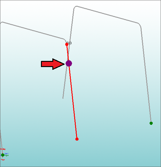
Enter 7 in the Move Amount field. You should see a PURPLe point on the leg of the third part. If your assembly project looks like the picture below, click the Apply button.
Now we need to do the same thing to the other side of the same part. Start by clicking the Set Reference button again.
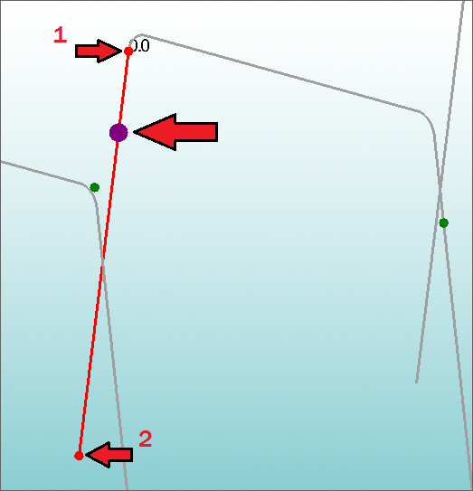
Hover over and click the end point of the arc of the last bend on the part (tangent of the last straight section), followed by the end point of the part. These are the same points you chose before but on the opposite side of the part.
Ensure you still have 7 entered in the Move Amount field and then click the Apply button. Your display window should look like the picture below.
Now we will shorten the legs of the third part to these new PickPoints we just created.
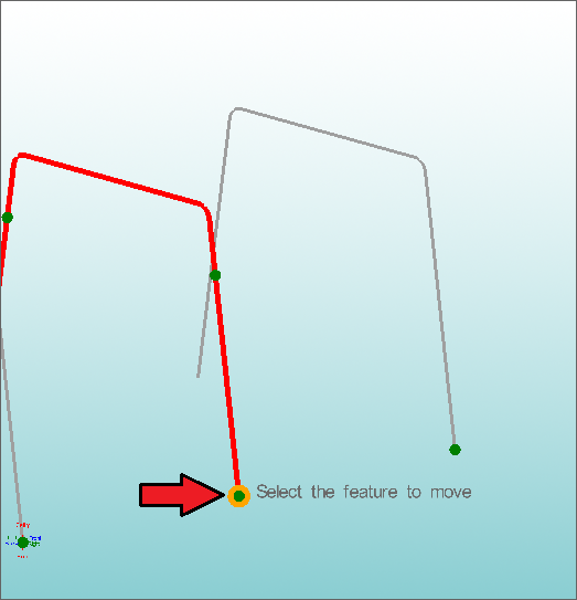
Go to the Edit Tab and click on the Move Feature button.
Move Feature allows you to move a single feature of a part without moving the rest of the part. In order to use this function, you need to select the part you wish to edit first, followed by the feature on the part.
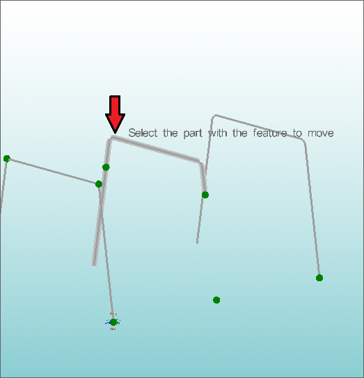
Hover over the third part and you should notice the entire part is highlighted. Click on this part as you see in the picture below.
Next, hover over and click the bottom right point.
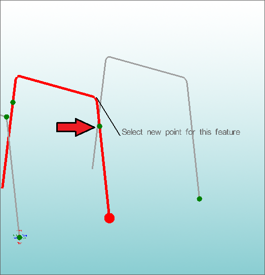
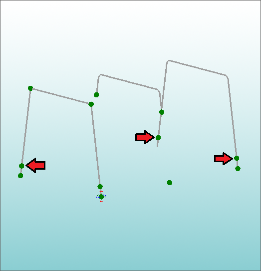
Now you should the leg of the part attached to your cursor. We now need to select the new PickPoint we created a few steps ago as the new end point of this leg. You should see two PickPoints on the third part. For this leg, we need to select the right-most point.
Hover over and select the PickPoint on the right leg as shown below. The leg of the part will now be shortened.
You must now shorten the other leg in the same fashion as the first.
Click the Move Feature button again and click on the middle part to select the part.
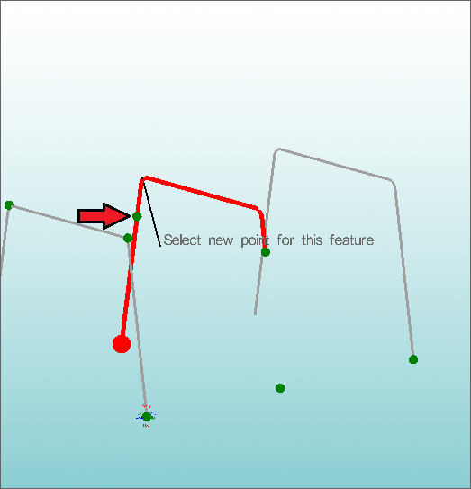
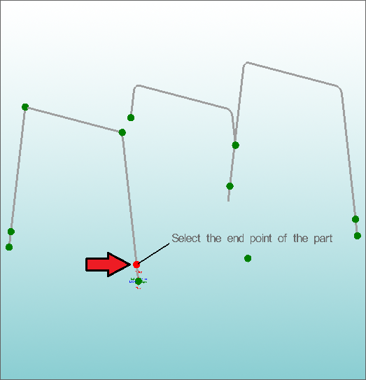
Hover over and click the point at the end of the part, as indicated in the picture below.
Hover over and select the PickPoint on the left leg as shown below. The leg of the part will now be shortened.
It is now time to add our 2 horizontal rungs to our assembly.
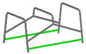
As seen in the picture below, the rungs are up 4 inches from the bottom of the assembly.
Because the first and second parts’ legs are not straight up (slanted in) the PickPoint Line function will not work. Remember the PickPoint Line function is a distance down a line. In this case we want to go straight up 4 inches and don’t know how far down the leg that will be.
Go to the PickPoints Tab.
Select the Plane / Arc Tab.
When using the Plane function, we need to define which plane we will be using. In this case, we will be using the default Z Plane (parallel to the ground) and then defining a line to intersect this plane. We also need to select a base point of the plane. In our case, our plane will be 4 inches up from the ground so we will use the point at the end of the part.
Ensure the Z Plane is selected under the Plane section.
Click the Set Base Point button.
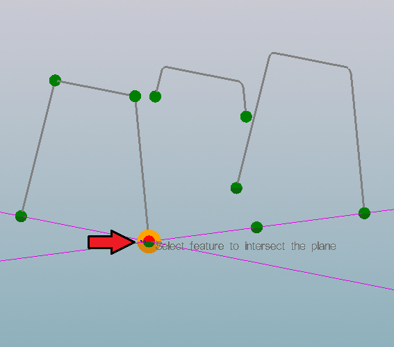
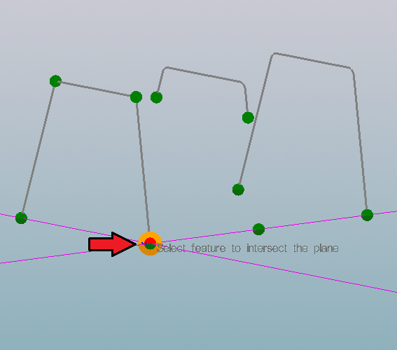
Select the PickPoint on the right leg of the first part as shown in the picture below. This point will be the base point of the plane.
You will see a circular pattern appear around this PickPoint. This pattern represents the plane we are working with.
The direction of the plane is determined by the Plane option. In our case the default Z Plane is the correct plane.
Also, the plane is currently at ground level, but we want to move the plane to the ceiling 4 inches.
Enter 4 into the Move Amount field. You will notice the plane is now 4 inches above the base point we selected.
Next we need to define the line that will intersect our plane. The intersection of the line and the plane will create a new point.
Select the Select Feature button.
Select the PickpPoint at the start of the leg (this is the same point you picked for the plane and is also the Tri-Star point).
Select the point at the beginning of the first bend (shown below).
Your screen should look like the picture below. Click the Apply button.
You must now repeat this process on the other three legs.
For each of the three legs:
-Click the Set Feature button.
-Select the bottom point of the leg.
-Click the point at the beginning of the bend on that leg.
-Click the Apply button to create the point.
Make sure you do the above four steps for each of the three remaining legs as shown below.
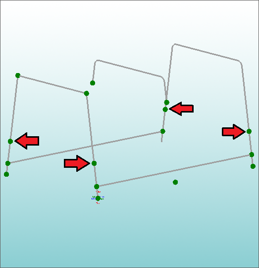
After all four points have been created using the Plane function, your screen should look like the picture below (notice the four points slightly above the ends of the two outside parts).
Now that we have our PickPoints defined it is time to make our rungs.
Select the Straight command button at the top of the assembly window.
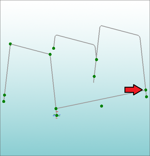
Select the first new PickPoint as shown in the picture below.
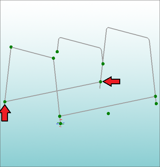
Click on the PickPoint that will be the opposite end of the first rung. Your screen should look like the picture below.
Next, create the second rung at the opposite side of the assembly. Your Screen should look like the picture below.
The final four parts we need to create are also straight parts.
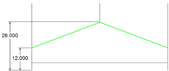
As before, we know the locations based upon from the floor to the ceiling.
The picture below shows us enough dimensions to finish.
Select the PickPoints Tab.
Select the Plane / Arc Tab.
You will now need to repeat the exact same process that we used to create the last four PickPoints. The only difference is that now you will need to have 12 in the Move Amount field instead of 4.
Enter 12 into the Move Amount field.
Select Set Base Point and then select the Tri-Star PickPoint.
You will notice our new plane 12 inches above the Tri-Star.
Select the Select Feature button and then select the two points on each leg of the outside parts.
After selecting each set of two points, make sure to click the Apply button to create the points. Repeat the process for all four legs.
When you are finished your screen should look like the picture below.
Now select the Straight button.
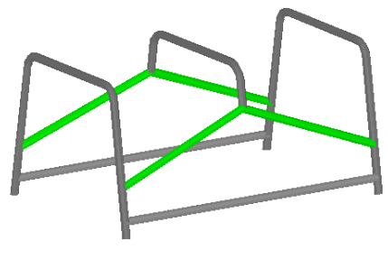
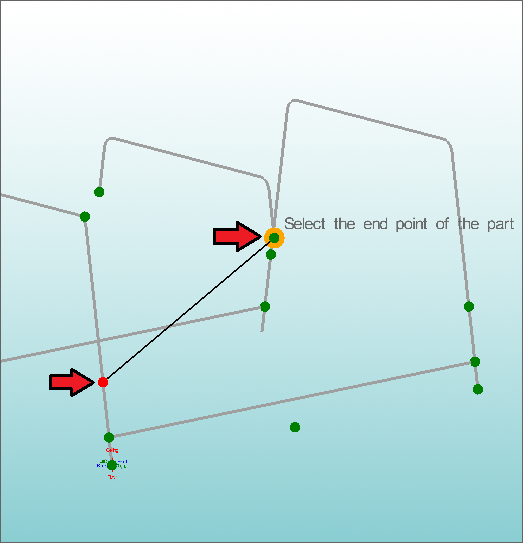
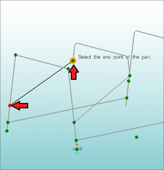
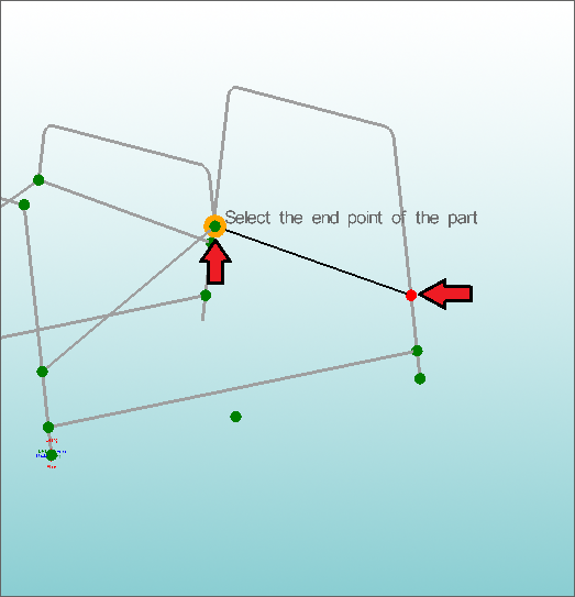
There are four parts left to be created. Each part is a line between one of the PickPoints you just created and one of the legs of the middle part (as shown below).
Look at the picture below to see which two PickPoints you should select for the first part.
Your screen should look like the picture below.
Repeat this process to create the remaining three parts. Refer to the picture below to see which points you need to select.
Here is our finished project. To see your project fully shaded like the picture below, click the little arrow next to the Display Mode button on the main toolbar and click on Shaded.
In order to save your project, select the File menu and select the Save button.
In the Save Assembly dialog, name the project whatever you wish and click the Save button. You are now finished with the assembly tutorial.
