Difference between revisions of "Calibration"
| Line 10: | Line 10: | ||
The best way to calibrate a new die when adding it to the die library is to use the Die Calibration Wizard. If you are already familiar with calibration process, you can use the quicker, simpler Die Worksheet. These can be found in the die library under the Help section. | The best way to calibrate a new die when adding it to the die library is to use the Die Calibration Wizard. If you are already familiar with calibration process, you can use the quicker, simpler Die Worksheet. These can be found in the die library under the Help section. | ||
Both the Calibration Worksheet and the Calibration Wizard will walk you through bending a simple test piece and measuring the results. These result will let the software calculate your calibration values you need for the dies in the software. | Both the Calibration Worksheet and the Calibration Wizard will walk you through bending a simple test piece and measuring the results. These result will let the software calculate your calibration values you need for the dies in the software. | ||
| − | Calibration Wizard | + | |
| + | ==Calibration Wizard== | ||
The Calibration Wizard will walk you through bending and measuring a test piece of material using the die you are trying to calibrate. The wizard is a step-by-step process and is recommended for those who are new to the software and/or calibrating dies. | The Calibration Wizard will walk you through bending and measuring a test piece of material using the die you are trying to calibrate. The wizard is a step-by-step process and is recommended for those who are new to the software and/or calibrating dies. | ||
| Line 18: | Line 19: | ||
Once a bender option has been chosen, follow the instructions very carefully. Remember to accurately measure and write down the cut length BEFORE bending the test piece! | Once a bender option has been chosen, follow the instructions very carefully. Remember to accurately measure and write down the cut length BEFORE bending the test piece! | ||
Use the Back and Next buttons to navigate through the instructions. After all these values have been entered, the achieved CLR, calibrated CLR, and bend location offset values will be generated. Click the Add Die button to add these values to current die in the die library. | Use the Back and Next buttons to navigate through the instructions. After all these values have been entered, the achieved CLR, calibrated CLR, and bend location offset values will be generated. Click the Add Die button to add these values to current die in the die library. | ||
| − | Calibration Worksheet | + | |
| + | ==Calibration Worksheet== | ||
If you are familiar with the test process and simply need the software to calculate the results, you can use the simpler Calibration Worksheet. | If you are familiar with the test process and simply need the software to calculate the results, you can use the simpler Calibration Worksheet. | ||
Revision as of 14:32, 3 July 2014
Contents
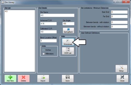
Die Details
Die Name: The die name is the name that will be assigned to the die. This name will be used to refer to this specific die everywhere in the software. Achieved CLR: The achieved CLR is the centerline radius of the die that compensates for any spring back. This value is usually slightly larger than the die size CLR. Calibrated CLR: The Calibrated CLR is the used in the software to determine the amount of stretch or growth in the bending process for that material and die. Bend Location Offset: The Bend Location Offset (BLO) is the distance added to the bend locations to offset the difference between the line-up mark on the die or bender to the true start of bend. Units: The unit type selection lets you specify whether the values you entered for the die are in inch units or millimeters. This option is only available in Bend-Tech SE.
Calibration Values
The best way to calibrate a new die when adding it to the die library is to use the Die Calibration Wizard. If you are already familiar with calibration process, you can use the quicker, simpler Die Worksheet. These can be found in the die library under the Help section. Both the Calibration Worksheet and the Calibration Wizard will walk you through bending a simple test piece and measuring the results. These result will let the software calculate your calibration values you need for the dies in the software.
Calibration Wizard
The Calibration Wizard will walk you through bending and measuring a test piece of material using the die you are trying to calibrate. The wizard is a step-by-step process and is recommended for those who are new to the software and/or calibrating dies.
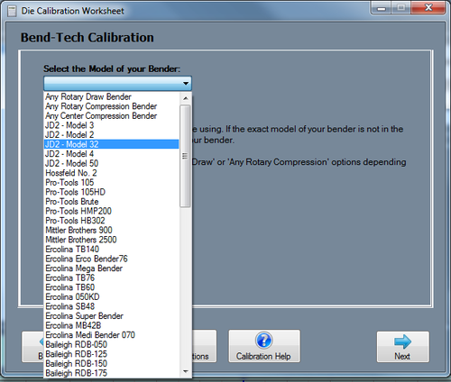
Follow the on-screen instructions when using the wizard. It is recommended to select the View Instructions button in order to print out the full instructions. This way you will not need to return to the computer multiple times during the test process. The printed sheet will also provide you with the space to write your test results. The first step is to pick your bender from the drop-down menu at the top of the window. If you cannot find your bender (or a bender similar to yours), just select the Any Rotary Draw, Any Rotary Compression or Any Center Compression option from this list.
Once a bender option has been chosen, follow the instructions very carefully. Remember to accurately measure and write down the cut length BEFORE bending the test piece! Use the Back and Next buttons to navigate through the instructions. After all these values have been entered, the achieved CLR, calibrated CLR, and bend location offset values will be generated. Click the Add Die button to add these values to current die in the die library.
Calibration Worksheet
If you are familiar with the test process and simply need the software to calculate the results, you can use the simpler Calibration Worksheet.
Simply fill in the required fields and the software will calculate the results. Once you are happy with the results, you can select the Add Die button to add the results to your die library.
OEM Die List
If you simply wish to start designing your parts and are not concerned with obtaining accurate bending results, you may choose to use the OEM Die List. This list contains the standard dies for some of the most common benders. The calibration values for these dies are a close estimate and can be used for designing parts in the software. However, it is strongly recommended to perform an actual calibration test (using the wizard or worksheet mentioned above) before using these dies to bend any parts.
If you find yourself having any trouble with a die from the OEM List, you will need to perform a calibration test yourself.
Once a bender option has been chosen, follow the instructions very carefully (Click the Print Instructions button to get a print out of the steps). Remember to accurately measure and write down the cut length BEFORE bending the test piece!
These steps require you to bend a test piece of material to 90 degrees. Use the Back and Next buttons to navigate through the instructions. After all these values have been entered, the achieved CLR, calibrated CLR, and bend location offset values will be generated. Click the Add Die button to add these values to current die in the die library.

