Difference between revisions of "Dimensions Tutorial"
| (20 intermediate revisions by the same user not shown) | |||
| Line 1: | Line 1: | ||
| − | + | '''This tutorial will show how to place dimensions on an assembly and a plate project.''' | |
| − | Start | + | ==Start Up== |
| − | [[File: | + | 1) Start by double clicking the "'''Bend-Tech 7x'''" icon to start up the program.[[File:Bend_tech_icon.png]] |
| − | + | 2) Select the "'''Assembly'''" icon [[File:Assembly_1_icon.png]] in the [[Task Menu]] under the "'''Create New'''" section to open the Assembly interface. The window that opens should be labeled [Assembly - 1].[[File:NewPartIcon3.jpg|right]] | |
| − | + | '''OR''' | |
| − | [[File: | + | 3) Select the New Part icon at the top of the window or select File --> New --> Assembly. |
| + | |||
| + | 4) For the purposes of this tutorial. The "'''Die & Material'''" tab is located in the upper left corner of the window. Select the "'''1.00 Material'''" and "'''2.0 Die'''" as seen here. | ||
| + | |||
| + | [[File:Material_Die.png]] | ||
| + | |||
| + | Note: If a default die and material have already been set up, they will already be selected. In that case proceed to the next step. | ||
| − | + | ==Creating a Part== | |
| − | + | '''Before we can create dimensions, we need to create a part to measure.''' | |
| − | + | 1. Go to the "'''PickPoints'''" tab. | |
| − | [[File: | + | [[File:WT2.JPG]] |
| − | + | 2. Select the "'''Set Reference'''" button and click the point at the center of the Tri-Star (this should be the only point on the screen right now). If you successfully select the point, it will turn red. Type "'''24'''" in the light green "'''Right'''" value field. Click the "'''Apply'''" button. | |
| − | [[File: | + | [[File:WT41.JPG]] |
| − | + | 3. Select the "'''Clear Values'''" button. Type "'''12'''" in the light green "'''Right'''" value field and click "'''Apply'''". | |
| − | [[File: | + | [[File:WT51.JPG]] |
| − | + | 4. Leave "'''12'''" in the right value field and type "'''8'''" in the dark blue "'''Front'''" field. Click the Apply button. | |
| − | [[File: | + | [[File:WT61.JPG]] |
| − | + | 5. Delete the value in the front field and type in "'''12'''". Select the "'''Apply'''" button. | |
| − | [[File: | + | [[File:WT71.JPG]] |
| − | + | 6. Select the "'''Straight Part'''" button. Click the two points that are indicated in the picture below. | |
[[File:WT10.JPG]] | [[File:WT10.JPG]] | ||
| − | Click the two points that are indicated in the picture below. | + | 7. Click the two points that are indicated in the picture below. |
[[File:WT11.JPG]] | [[File:WT11.JPG]] | ||
| − | Click the two points that are indicated in the picture below. | + | 8. Click the two points that are indicated in the picture below. |
[[File:WT12.JPG]] | [[File:WT12.JPG]] | ||
| − | You are now finished building the part. | + | '''You are now finished building the part.''' |
| − | + | *To see the material added to the part, select the "'''Display'''" button on the "'''Main Menu'''" toolbar. | |
| − | + | ==Part Dimensions== | |
| − | + | 1. Go to the "'''Dimensions'''" tab. Select the "'''2D Mode'''" button. | |
| − | [[File: | + | [[File:WT19.JPG]] [[File:WT25.jpg]] |
| − | + | *To move the three views further away from each other, type larger values into the "'''Horizontal and Vertical Spacing'''" value fields. Since two of the views are no longer displayed, don't bother changing their spacing. More information on the dimension settings can be found in the user manual. | |
| − | + | 2. Select the "'''Horizontal'''" button. | |
| − | + | [[File:WT22.JPG]] | |
| − | + | 3. Now, click any two "'''PickPoints'''" to place a dimension that measures the horizontal distance between the points. Select the middle left point, followed by the right point. You will see a horizontal line with arrows at the ends. This is your dimension line. | |
| + | *If you move your cursor up or down, you will see vertical lines drawn between the points that you selected and the ends of the arrows. These lines are the extension lines. Move the cursor up until the dimension line is above the top point. | ||
| − | + | 4. You will see "'''Select location for text'''" attached to the left and right movement of the cursor. Move it until it is centered and click to place the dimension. | |
| − | + | [[File:WT231.Png]] | |
| − | + | *Vertical dimensions work exactly the same, except they measure the vertical distance between two points. Linear dimensions measure the distance between two points. It differs from Vertical or Horizontal because it measures in a straight line between the points, even if the points aren't aligned vertically or horizontally. | |
| − | + | 5. Select the Linear button. | |
[[File:WT24.JPG]] | [[File:WT24.JPG]] | ||
| − | + | 6. Select the bottom PickPoint followed by the right PickPoint. Move the cursor down and to the right slightly so that the dimension is out of the way. Click to place the dimension. | |
| − | [[File: | + | [[File:WT251.png]] |
| − | Angle allows you to measure an angle by selecting two intersecting lines. To place an angle dimension, | + | 7. Angle allows you to measure an angle by selecting two intersecting lines. To place an angle dimension, select the "'''Angle'''" button. |
| + | *In order to place an angle dimension, you have to select two intersecting lines. To select a line, you must select its outside and inside point. The inside point should always be the point that is closer to the second line. | ||
| − | + | 8. Click the middle left point, followed by the point that is in between the middle left and the right points. | |
| − | + | [[File:WT261.png]] | |
| − | + | 9. Now click the bottom point followed by the point that is in between the middle left and right points. Move the cursor down and to the left a bit so the dimension is out of the way. Click to place the dimension. | |
| + | *If our dimension was measuring the angle in the opposite direction (for example if it was measuring a 90° angle as being 270°) you could flip the angle by checking the "'''Flip Angle'''" checkbox before placing the dimension. Since our dimension is correct, leave the "'''Flip Angle'''" checkbox blank. | ||
| − | + | [[File:WT271.png]] | |
| + | 10. Move the dimension by selecting the "'''Move'''" button in the "'''Edit'''" area. | ||
[[File:WT28.JPG]] | [[File:WT28.JPG]] | ||
| − | Click the dimension you desire to bind it to your cursor. Once you have picked up a dimension, you can reposition it by using your cursor and place it by clicking. | + | 11. Click the dimension you desire to bind it to your cursor. Once you have picked up a dimension, you can reposition it by using your cursor and place it by clicking. |
| − | [[File: | + | [[File:WT421.png]] |
| − | To delete a dimension, | + | 12. To delete a dimension, select the "'''Delete'''" button and then click the grey dot that appears next to the dimension you want to delete. Delete the horizontal dimension we made. |
[[File:WT43.JPG]] | [[File:WT43.JPG]] | ||
| − | The Edit Value button allows you to change the displayed value of a dimension. | + | 13. The "'''Edit Value'''" button allows you to change the displayed value of a dimension. Select the "'''Edit Value'''" button, click on the grey dot next to the dimension you want to edit, and enter a new value in the window that appears. |
| − | The | + | *The "'''Settings'''" section allows you to edit the properties of a dimension. The table on the bottom of the Dimensions tab lists all of the dimension properties and their current value/setting. See the user manual for information on the dimension properties. Change any of the dimensions properties that you want to by clicking on the value column in the settings box and either entering a new value or selecting a new option from the drop down menu. Select the "'''Apply'''" button to apply the changes to that dimension, or select the "'''Apply to All'''" button to apply the changes to all of the dimensions that you have placed. |
| − | Try changing the arrow type of the linear dimension to Double. To do so, | + | 14. Try changing the arrow type of the linear dimension to "'''Double'''". To do so, select the "'''Arrow Type'''" drop down menu in the "'''Settings'''" section and select "'''Double'''", followed by the grey dot next to the linear dimension that reads "14.42". |
[[File:WT44.JPG]] | [[File:WT44.JPG]] | ||
| − | + | *In the Dimensions window, check the "'''Display PickPoints'''" check box to show PickPonts within the display area. | |
| + | |||
| + | *To print a view of your dimensions, select the "'''Print'''" icon on the top of your screen. From there you can choose "'''Multi Page'''" or "'''Single Page'''" for your printing options. Multi Page will print each view of your part separately, while Single Page will print all three views on one page. | ||
| + | |||
| + | [[File:WT24.jpg]] [[File:WT23.jpg]] | ||
| − | You are now finished with the Dimensions Tutorial. | + | '''You are now finished with the Dimensions Tutorial.''' |
Latest revision as of 10:18, 19 September 2014
This tutorial will show how to place dimensions on an assembly and a plate project.
Start Up
1) Start by double clicking the "Bend-Tech 7x" icon to start up the program.![]()
OR
3) Select the New Part icon at the top of the window or select File --> New --> Assembly.
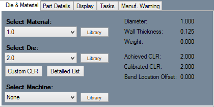
4) For the purposes of this tutorial. The "Die & Material" tab is located in the upper left corner of the window. Select the "1.00 Material" and "2.0 Die" as seen here.
Note: If a default die and material have already been set up, they will already be selected. In that case proceed to the next step.
Creating a Part
Before we can create dimensions, we need to create a part to measure.
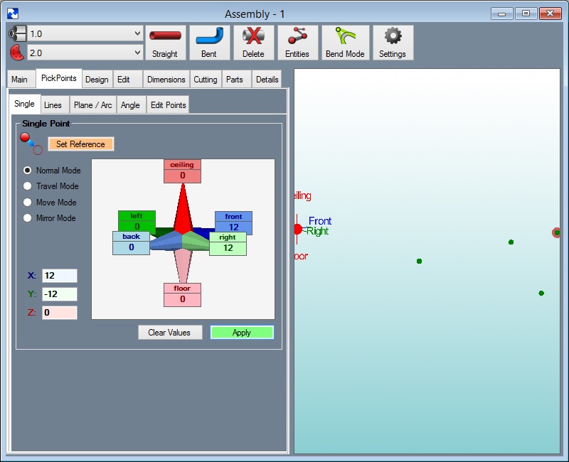
1. Go to the "PickPoints" tab.
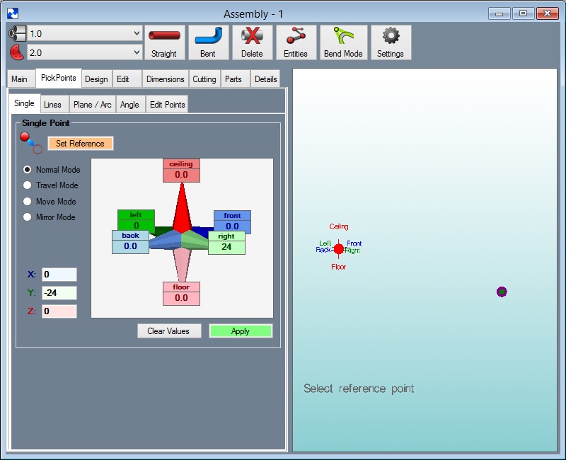
2. Select the "Set Reference" button and click the point at the center of the Tri-Star (this should be the only point on the screen right now). If you successfully select the point, it will turn red. Type "24" in the light green "Right" value field. Click the "Apply" button.
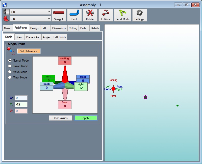
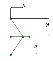
3. Select the "Clear Values" button. Type "12" in the light green "Right" value field and click "Apply".
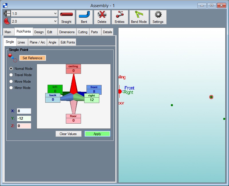
4. Leave "12" in the right value field and type "8" in the dark blue "Front" field. Click the Apply button.
5. Delete the value in the front field and type in "12". Select the "Apply" button.
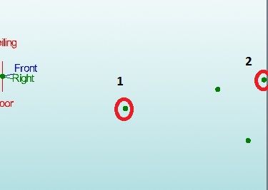
6. Select the "Straight Part" button. Click the two points that are indicated in the picture below.
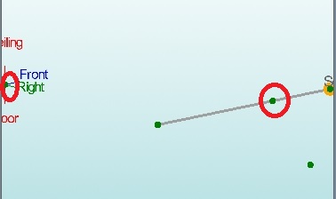
7. Click the two points that are indicated in the picture below.
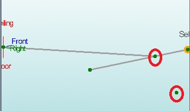
8. Click the two points that are indicated in the picture below.
You are now finished building the part.
- To see the material added to the part, select the "Display" button on the "Main Menu" toolbar.
Part Dimensions
1. Go to the "Dimensions" tab. Select the "2D Mode" button.
- To move the three views further away from each other, type larger values into the "Horizontal and Vertical Spacing" value fields. Since two of the views are no longer displayed, don't bother changing their spacing. More information on the dimension settings can be found in the user manual.
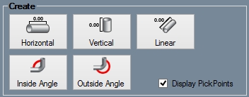
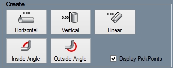
2. Select the "Horizontal" button.
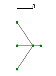
3. Now, click any two "PickPoints" to place a dimension that measures the horizontal distance between the points. Select the middle left point, followed by the right point. You will see a horizontal line with arrows at the ends. This is your dimension line.
- If you move your cursor up or down, you will see vertical lines drawn between the points that you selected and the ends of the arrows. These lines are the extension lines. Move the cursor up until the dimension line is above the top point.
4. You will see "Select location for text" attached to the left and right movement of the cursor. Move it until it is centered and click to place the dimension.
- Vertical dimensions work exactly the same, except they measure the vertical distance between two points. Linear dimensions measure the distance between two points. It differs from Vertical or Horizontal because it measures in a straight line between the points, even if the points aren't aligned vertically or horizontally.
5. Select the Linear button.
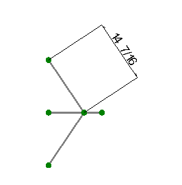
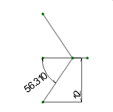
6. Select the bottom PickPoint followed by the right PickPoint. Move the cursor down and to the right slightly so that the dimension is out of the way. Click to place the dimension.
7. Angle allows you to measure an angle by selecting two intersecting lines. To place an angle dimension, select the "Angle" button.
- In order to place an angle dimension, you have to select two intersecting lines. To select a line, you must select its outside and inside point. The inside point should always be the point that is closer to the second line.
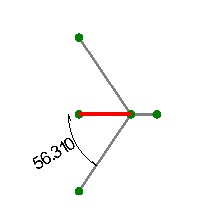
8. Click the middle left point, followed by the point that is in between the middle left and the right points.
9. Now click the bottom point followed by the point that is in between the middle left and right points. Move the cursor down and to the left a bit so the dimension is out of the way. Click to place the dimension.
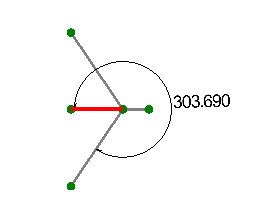
- If our dimension was measuring the angle in the opposite direction (for example if it was measuring a 90° angle as being 270°) you could flip the angle by checking the "Flip Angle" checkbox before placing the dimension. Since our dimension is correct, leave the "Flip Angle" checkbox blank.
10. Move the dimension by selecting the "Move" button in the "Edit" area.

11. Click the dimension you desire to bind it to your cursor. Once you have picked up a dimension, you can reposition it by using your cursor and place it by clicking.
12. To delete a dimension, select the "Delete" button and then click the grey dot that appears next to the dimension you want to delete. Delete the horizontal dimension we made.
13. The "Edit Value" button allows you to change the displayed value of a dimension. Select the "Edit Value" button, click on the grey dot next to the dimension you want to edit, and enter a new value in the window that appears.
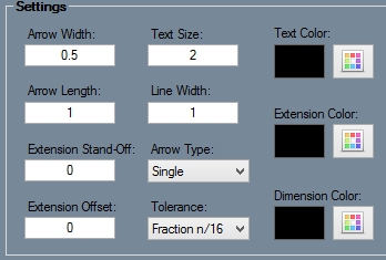
- The "Settings" section allows you to edit the properties of a dimension. The table on the bottom of the Dimensions tab lists all of the dimension properties and their current value/setting. See the user manual for information on the dimension properties. Change any of the dimensions properties that you want to by clicking on the value column in the settings box and either entering a new value or selecting a new option from the drop down menu. Select the "Apply" button to apply the changes to that dimension, or select the "Apply to All" button to apply the changes to all of the dimensions that you have placed.
14. Try changing the arrow type of the linear dimension to "Double". To do so, select the "Arrow Type" drop down menu in the "Settings" section and select "Double", followed by the grey dot next to the linear dimension that reads "14.42".
- In the Dimensions window, check the "Display PickPoints" check box to show PickPonts within the display area.
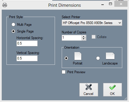
- To print a view of your dimensions, select the "Print" icon on the top of your screen. From there you can choose "Multi Page" or "Single Page" for your printing options. Multi Page will print each view of your part separately, while Single Page will print all three views on one page.
You are now finished with the Dimensions Tutorial.
