Difference between revisions of "Custom Part Tutorial"
| (6 intermediate revisions by the same user not shown) | |||
| Line 1: | Line 1: | ||
| − | |||
'''This tutorial will walk you through how to start and create a part using the custom part interface.''' | '''This tutorial will walk you through how to start and create a part using the custom part interface.''' | ||
| − | + | ||
==Start Up== | ==Start Up== | ||
| − | 1) Start by double clicking the "'''Bend-Tech 7x'''" icon to start up the program.[[File:Bend_tech_icon.png | + | 1) Start by double clicking the "'''Bend-Tech 7x'''" icon to start up the program.[[File:Bend_tech_icon.png]] |
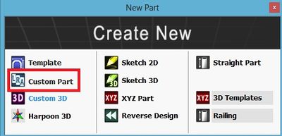
| − | 2) Select the "'''Custom Part'''" icon [[File: | + | 2) Select the "'''Custom Part'''" icon [[File:Custom_Part_icon1.png]] in the [[Task Menu]] under the "'''Create New'''" section to open the Custom Part interface. The window that opens should be labeled [Custom Part - 1].[[File:NewPartIcon2.jpg|right]] |
'''OR''' | '''OR''' | ||
| Line 14: | Line 13: | ||
*In the "'''New Design'''" menu, select the "'''Custom Part'''" option under "'''Create New Design'''". | *In the "'''New Design'''" menu, select the "'''Custom Part'''" option under "'''Create New Design'''". | ||
| + | [[File:CustomNewDesign.jpg|400px]] | ||
| − | |||
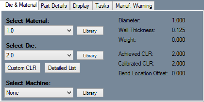
4) For the purposes of this tutorial. The "'''Die & Material'''" tab is located in the upper left corner of the window. Select the "'''1.00 Material'''" and "'''2.0 Die'''" as seen here. | 4) For the purposes of this tutorial. The "'''Die & Material'''" tab is located in the upper left corner of the window. Select the "'''1.00 Material'''" and "'''2.0 Die'''" as seen here. | ||
| − | [[File: | + | [[File:Material_Die.png]] |
Note: If a default die and material have already been set up, they will already be selected. In that case proceed to the next step. | Note: If a default die and material have already been set up, they will already be selected. In that case proceed to the next step. | ||
| Line 25: | Line 24: | ||
==Creating a Custom Part== | ==Creating a Custom Part== | ||
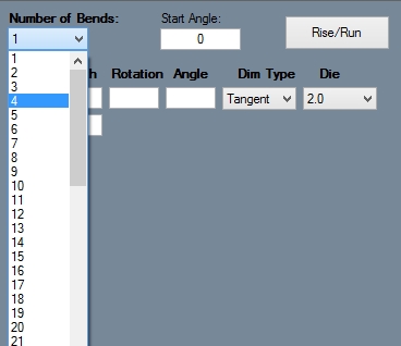
| − | 1 | + | 1. Once a proper die and material have been selected, the custom part design panel will be available to edit. First, the number of bends needs to be chosen. Select the drop down menu below "'''Number of Bends'''" and select "'''4'''" from the list. |
[[File:NumberBends.jpg]] | [[File:NumberBends.jpg]] | ||
| − | 2 | + | 2. Make sure the box next to "'''Refresh on Keystroke'''" is checked. While this option is enabled, the part display and results table will update automatically as the coordinates are being entered. |
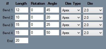
| − | 3 | + | 3. In the coordinate fields, type in the values that are shown below. Make sure each bend's Dim Type is set to Apex. If not, select the drop down menu and select Apex from the list. |
[[File:CustomCoordinates.jpg]] | [[File:CustomCoordinates.jpg]] | ||
| − | 4 | + | 4. Once these values have been entered, the window should look similar to the image below. '''The part is now complete'''. The results table for the complete part is shown in the top right corner. |
[[File:TutorialCustomPart.jpg|600px]] | [[File:TutorialCustomPart.jpg|600px]] | ||
Latest revision as of 09:17, 22 September 2014
This tutorial will walk you through how to start and create a part using the custom part interface.
Start Up
1) Start by double clicking the "Bend-Tech 7x" icon to start up the program.![]()
OR
3) click the New Part icon at the top of the window or select File --> New --> Tube. Doing so will bring up the "New Design Menu". This menu will also appear automatically when Bend-Tech starts up.
- In the "New Design" menu, select the "Custom Part" option under "Create New Design".
4) For the purposes of this tutorial. The "Die & Material" tab is located in the upper left corner of the window. Select the "1.00 Material" and "2.0 Die" as seen here.
Note: If a default die and material have already been set up, they will already be selected. In that case proceed to the next step.
Creating a Custom Part
1. Once a proper die and material have been selected, the custom part design panel will be available to edit. First, the number of bends needs to be chosen. Select the drop down menu below "Number of Bends" and select "4" from the list.
2. Make sure the box next to "Refresh on Keystroke" is checked. While this option is enabled, the part display and results table will update automatically as the coordinates are being entered.
3. In the coordinate fields, type in the values that are shown below. Make sure each bend's Dim Type is set to Apex. If not, select the drop down menu and select Apex from the list.
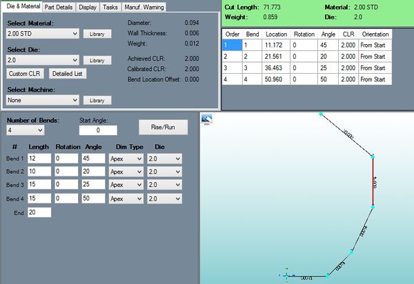
4. Once these values have been entered, the window should look similar to the image below. The part is now complete. The results table for the complete part is shown in the top right corner.
- To adjust any settings, view the bend order, or to see any warnings, click any of the tabs the tabbed section at the top of the design window.
- The part can be saved by selecting the save icon or by clicking File --> Save in the main menu bar. The setup sheet for the part can be printed by clicking the print icon or by clicking File --> Print.
