Difference between revisions of "Sheet Metal Text"
| (2 intermediate revisions by the same user not shown) | |||
| Line 66: | Line 66: | ||
5. The user also has the option to create a text section that contains a curve. The rotation of the curve is set by the user in the "'''Arc Radius:'''" value field. | 5. The user also has the option to create a text section that contains a curve. The rotation of the curve is set by the user in the "'''Arc Radius:'''" value field. | ||
| − | ==Bridging Path Text== | + | ==[[Bridging]] Path Text== |
| Line 83: | Line 83: | ||
| − | 3. In order to use this feature, make sure that the "'''Free Select'''" button is enabled. | + | 3. In order to use this feature, make sure that the "'''Free Select'''" [[File:Freeselect1.png]] button is enabled. |
Latest revision as of 14:16, 15 December 2014
Sheet Metal Text
- This tutorial will begin by showing how to create a specified piece of sheet metal with text included.
- "If you're not familiar with this interface, it is suggested that you visit the Sheet Metal Module page for better understanding of the basics."
Start Up
1) Start by double clicking the "Bend-Tech 7x" icon to start up the program.![]()
2) Select the "Plate" icon ![]() in the Task Menu under the "Create New" section to open the Sheet Metal/Plate interface, OR... select the Plate button on the main toolbar, OR... select File → New → Plate.
The window that opens should be labeled [Plate - 1].
in the Task Menu under the "Create New" section to open the Sheet Metal/Plate interface, OR... select the Plate button on the main toolbar, OR... select File → New → Plate.
The window that opens should be labeled [Plate - 1].
3) For the purposes of this tutorial, click the "Maximize" button ![]() at the top right of the plate design window.
at the top right of the plate design window.
4) Also, for the purposes of this tutorial, zoom out significantly by spinning the wheel on your mouse so that the Tri-star is about the size of a pea in the lower left corner of the display area.
Creating a Part
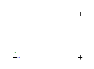
1. Start by selecting the "Incremental" option under the "Create--> Point" tab and entering "12" into the "Y" value field.
2. Now, select the base point to create a point 12 inches upwards of it.
3. Next, delete the "12" and replace it with "0" and enter the number "18" in the "X" value field. Then, click on the base point and the point 12 inches
above it as well. This will create the four points of the rectangular base flange we will be working on.
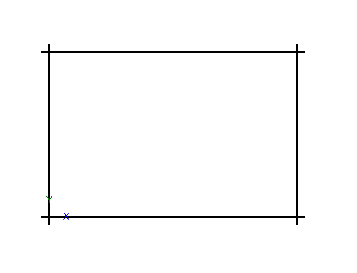
4. Select the "Line" tab and click on the continuous option. Then, select each of the four points in a row to create a rectangle. This is the base flange that we will be working with for the purposes of this tutorial.
5. Lastly, select the "Part--> Definition" tab and select "Material .25" to define the flange.
"(Note) If users have not already created a material in this interface, it is suggested that our they complete the Plate Tutorial first."
Introducing Path Text Into a Part
1. Select the "Create--> Text" and select the "New Text" button near the top.
2. Select the "Path (Outline)" option and type "Bend-Tech" in the "Text Properties" field.
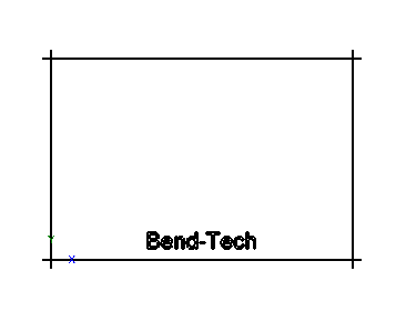
3. With Path Text, the letters will be stacked on top of each other unless the user adjusts the "Horizontal Stretch:" function in the "Text Layout" section. Type "1" in the "Horizontal Stretch:" value field and place the words on the bottom of the flange in the center as shown here.
4. Please note that the "Edit Text, Move Text and Delete Text" buttons do not work on Path Text. They are meant for "Normal" Text only. Any adjustments made to Path Text must be determined before the user places the wording into the display area. Deleting Path Text can only be done by using the "Undo" button under the "Edit" tab or by going to the "Edit--> Delete" tab and deleting by selecting the "Window" option, using that to surround the text, and selecting the "Complete" button.
5. The user also has the option to create a text section that contains a curve. The rotation of the curve is set by the user in the "Arc Radius:" value field.
Bridging Path Text
1. In the process of cutting out the text in a piece of sheet metal, you'll notice that the holes made by certain letters may not look optimal as they are entered within the software. They require "Bridging" so that letters like "B, O, P, D, Q, R, and other letters with closed loops" will look presentable on the user's finished product.
2. Define the flange first in "Part--> Definition" and then go to "Create--> Misc--> Bridge" to access the Bridging function.
3. In order to use this feature, make sure that the "Free Select" ![]() button is enabled.
button is enabled.
4. Change the width to ".10" in the "Width:" value field and keep the "Auto Trim'" check box checked as well as the "Two Point Select" box.
5. Then, create a bridge over each closed-looped letter using the two-click process as seen in the picture to the right.


