Difference between revisions of "Sheet Metal Tutorial II"
| Line 174: | Line 174: | ||
[[File:Sheet30.png]] | [[File:Sheet30.png]] | ||
| + | |||
| + | 31. Now, switch over to the Delete sub-tab and delete the three excess lines from Flange 3. | ||
| + | |||
| + | [[File:Sheet31.png]] | ||
| + | |||
| + | 32. Define this flange under the Part tab and select the Display button above to see our project taking shape. | ||
| + | |||
| + | [[File:Sheet32.png]] | ||
| + | |||
| + | 33. Next, we will make some additional flanges so we have more space to fillet edges, add text, stitches and dimples. | ||
| + | |||
| + | ==Adding More Flanges and Filleting== | ||
| + | 34. Still under the part tab, Click on the Bends sub-tab and switch the Display back to the Design mode. | ||
| + | |||
| + | [[File:Sheet33.png]] | ||
| + | |||
| + | 35. Then, change the flange direction to Up, Type 24 into the Flange Initial Height field and add two new flanges on either side of our project. | ||
| + | |||
| + | [[File:Sheet34.png]] | ||
| + | |||
| + | 36. Then select the Definition sub-tab and click the Define All button. | ||
| + | |||
| + | [[File:Sheet35.png]] | ||
| + | |||
| + | 37. Now, to add some filleted arcs, select the Create tab and the Arc sub-tab. Then check the Auto-Trim check box. | ||
| + | |||
| + | [[File:Sheet36.png]] | ||
| + | |||
| + | 38. Next, select the right most flange from the list (it's labeled Flange 4 for me since I created it first) and create an arc by selecting the two intersecting lines in the top right corner. | ||
| + | |||
| + | [[File:Sheet37.png]] | ||
| + | |||
| + | 39. Then, select Flange 5 and do the same. | ||
Revision as of 12:03, 3 June 2015
This tutorial is designed to walk you through the steps in creating a part using the sheet metal module.
"IT IS CURRENTLY UNDER CONSTRUCTION. THANK YOU FOR YOU PATIENCE."
Sheet Metal/Plate Design
- This tutorial will begin by showing how to create a specified piece of bent sheet metal designed with "PickPoints".
- If you're not familiar with this interface, it is suggested that you visit the Sheet Metal Module and the Sheet Metal Tutorial pages for better understanding of the basics.
Things To Know
- This tutorial is designed to walk the user through creating a sheet metal/plate design. As you go through this tutorial, later procedures will assume that you understand all earlier procedures. Because of this, it is very important that you carefully step through this guide, understanding everything along the way and following all steps in order.
- A few key items need to be addressed before starting the step-by-step instructions of this tutorial. It is very important for Bend-Tech users to completely understand these items:
- 1) PickPoints
- PICKPOINTS ARE USED FOR EVERYTHING. The Sheet Metal part of the software is largely run in full 3D. Because a computer screen is only 2D, there is an unlimited amount of depth behind and in front of the cursor. A PickPoint is a point in 3D space that can be used for creating, editing, and placing parts in handrail design. PickPoints can be placed in a 2D environment by having their depth manually entered in the appropriate value fields.
- There are 2 types of PickPoints; Those automatically created by the part by default (various colors) and user-defined points (green). In addition, the initial (0,0,0) point is an automatic point that resides at the center of the Tri-Star. The Tri-Star is our directional definition locator.
- 2) Apex
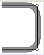
- Apex: Most bend locations are created in Sheet Metal design with the "Apex". Our definition of apex is the intersection of the straight parts as if there wasn’t a radius.
- This is demonstrated in the picture below.
- 3) Location Orientation
-
- Since there is no Tri-Star like in other tube bending interfaces, the only orientation users should worry about when designing in Sheet Metal, is a bird's eye view. This designer is set up so that users can imagine looking over their project as if it is on their table in front of them.
Start Up
1) Start by double clicking the "Bend-Tech 7x" icon to start up the program.![]()
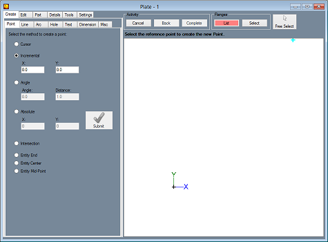
2) Select the "Plate" icon ![]() in the Task Menu under the "Create New" section to open the Sheet Metal/Plate interface, Or... select the Plate button on the main toolbar, OR... select "File → New → Plate".
The window that opens should be labeled [Plate - 1].
in the Task Menu under the "Create New" section to open the Sheet Metal/Plate interface, Or... select the Plate button on the main toolbar, OR... select "File → New → Plate".
The window that opens should be labeled [Plate - 1].
3) For the purposes of this tutorial, click the "Maximize" button ![]() at the top right of the plate design window.
at the top right of the plate design window.
Free Select
- Free Select
 can be used to allow the user to click anywhere on the screen as if there was a point. Whenever Free Select is on, the display window is dimmed slightly. It is very difficult to place points with precision using Free Select mode, so make sure you take it off whenever you are trying to do something where precision matters.
CAD vs Sheet Metal
- The Part Interface is basically divided into 2 areas, a simple CAD interface and sheet metal functions. The CAD functions allow you to create a part using points, lines, arcs, and other features for the part, much like other CAD software. These functions include trimming/extending lines, using tangent and intersection points, and placing dimensions. The sheet metal portion of the software allows you to convert features into a flange and add flanges together with bends.
Bending Radius
- When creating a bent part and setting up a material in the Plate Material Library, it is important to understand that the bending radius is the INSIDE radius of the bend. While some areas of the software may use the centerline dimensions, the bending radius of each bend on a sheet metal part is referring to the Inside Radius.
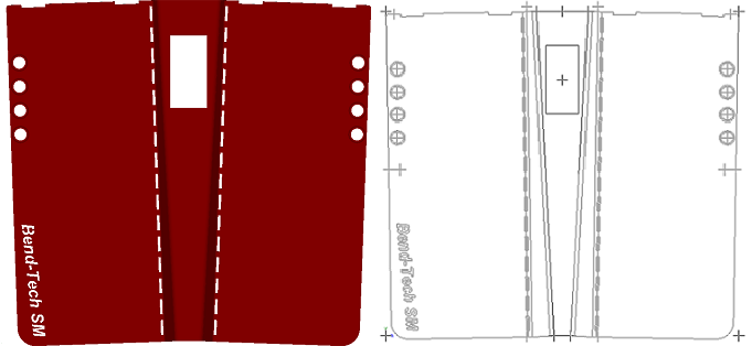
- The following image shows the part we will be building in this tutorial.
Creating Pickpoints
1. Start creating Pickpoints by selecting the Incremental option to the left under the Point sub-tab.
2. Now, type 62 into the X field and click on the origin to place a point.
3. Then, zero out the X field, type 57 into the Y field and select the Origin and the other bottom point to the right. This will create the profile of a rectangle as seen below.
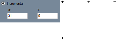
4. Now, zero out the Y field, type 31 into the X field and click the upper left point.
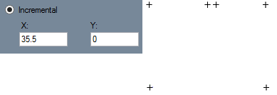
5. Then, change the X value to 35.5 and click the same point to the upper left.
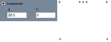
6. Place a minus sign in front of the X value and click the upper right point this time. Now, you should have all symmetrical points on the screen as shown in the picture below.
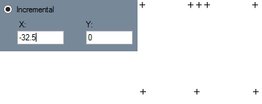
7. Now, change the X value to a negative 32.5 and click the bottom right point.
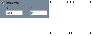
8. Finally, delete the minus sign in the X field and click the bottom left point.
Creating Lines
9. Now, to create our defined edges, select the Line sub-tab, click on the Continuous check box and connect the dots to make four lines as shown in the picture below.
10. To stop the continuous line, click on the Cancel button above the display area.
Applying Material
11. Click on the Part tab from above to apply a material.
12. Select the Library button and you'll see the Material list and the option to add a new material to the Library.
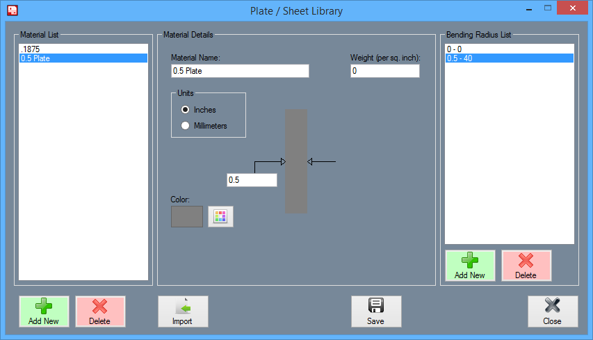
13. When the Plate/Sheet Library window opens, select the Add New button to the left in order to add a material.
14. Add a 0.5 inch material by typing in the information seen here and adding a new Bending Radius of 0.5-40. Save them both by clicking the Save button at the bottom of the window.
15. Select the Close button to close this window and select the material from the Material drop down menu. Then, click the Define Flange button and click just outside the part in order to define it.
Adding Flanges
16. Select the Bends sub-tab next to the Definition sub-tab.
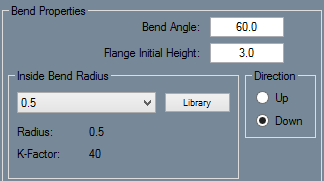
17. Change our bend angle to 60 degrees, our flange initial height to 3 inches and the direction to down. Then, select the point five inside bend radius from the drop down menu below.
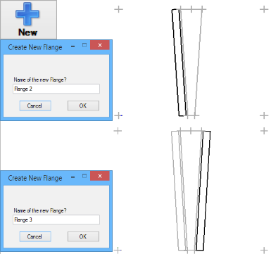
18. When these options are set, select the blue New button and click on both sides of our base flange in order to create two new flanges as seen below.
19. Then, switch back to the Definition sub-tab and click on the Define All button. All three flanges should immediately define as part of the project.
20. To check, select the Display button from above three times and you will view the part as a 3D model.
21. Now, we will attempt to trim back parts of these new flanges, but first we will place some points as references to draw additional lines.
More Points and Lines
22. Go to the Create tab and switch to the Point sub-tab.
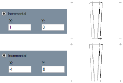
23. From here, use the Incremental tool and create points 1 inch outward from either side of the bottom edges of the part. Place a 1 in the X field and select the bottom outer edge of flange 3, then type a -1 in the X field and select the bottom outer edge of flange 2. (See pictures below)
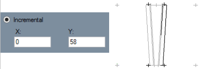
24. Then, zero out the X value field, type 58 into the Y field and select each of the new points to place new ones 58 inches above them.
25. Afterward, go to the Lines sub-tab and create two vertical lines by connecting the bottom edges of our part to the top new points as seen here. Make sure not to use the two newly created bottom points and that the flange you are working on is selected from the flanges list from above. Otherwise, it will not be added into the design as a legitimate line.
26. Now switch to the Edit tab and click the Trim sub-tab so we can trim back some unneeded lines from our project.
Breaking, Deleting and Re-Drawing Lines
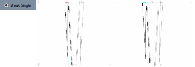
27. Working on Flange 2 first, start by selecting the Break Single option below and click on the line you want to break followed by the line you want to break it against.
28. Then, Switch to the Delete sub-tab and select the excess lines and click the Complete button above to erase them from the design. (Note: You could also use the Trim Single function to achieve the same goal.)
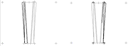
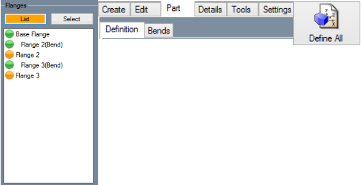
29. Now, select Flange 2 from the Flanges list above and switch to the Part tab to define it.
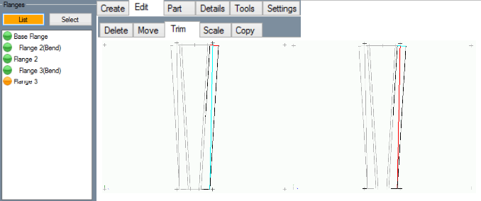
30. To fix the other side, change to Flange 3, click on the Edit tab, then the Trim sub-tab and follow the same method. Remember to break the lines both ways before deleting.
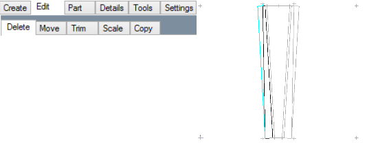
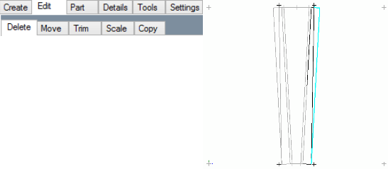
31. Now, switch over to the Delete sub-tab and delete the three excess lines from Flange 3.
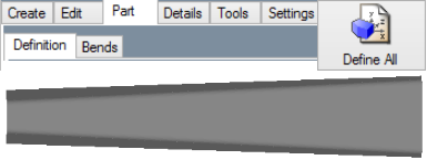
32. Define this flange under the Part tab and select the Display button above to see our project taking shape.
33. Next, we will make some additional flanges so we have more space to fillet edges, add text, stitches and dimples.
Adding More Flanges and Filleting
34. Still under the part tab, Click on the Bends sub-tab and switch the Display back to the Design mode.
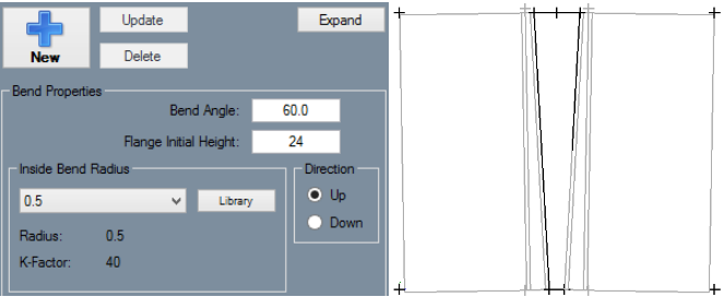
35. Then, change the flange direction to Up, Type 24 into the Flange Initial Height field and add two new flanges on either side of our project.
36. Then select the Definition sub-tab and click the Define All button.
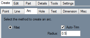
37. Now, to add some filleted arcs, select the Create tab and the Arc sub-tab. Then check the Auto-Trim check box.
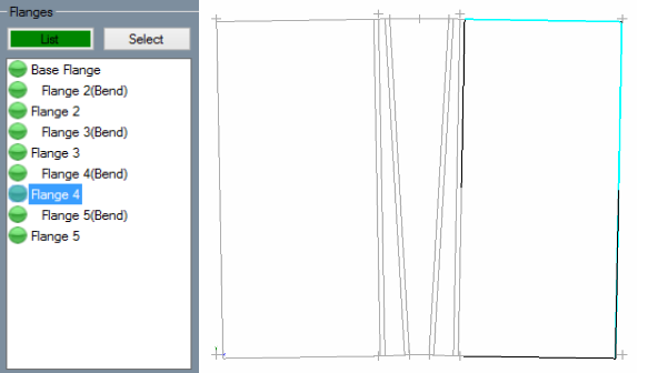
38. Next, select the right most flange from the list (it's labeled Flange 4 for me since I created it first) and create an arc by selecting the two intersecting lines in the top right corner.
39. Then, select Flange 5 and do the same.
