Difference between revisions of "Creating PickPoints using Angle & Plane"
| (2 intermediate revisions by the same user not shown) | |||
| Line 5: | Line 5: | ||
I started by creating my 1st hoop as you described. Please note I made it in Assembly. If you haven't, go through the "Assembly Tutorial" under your bend-tech "Help" menu. | I started by creating my 1st hoop as you described. Please note I made it in Assembly. If you haven't, go through the "Assembly Tutorial" under your bend-tech "Help" menu. | ||
| − | Step 1 | + | '''Step 1:''' I created two PickPoints coming off of my tangent points from the 1st hoop. Please note; the model is back-wards (front to back) compared to your picture. |
[[File:AnglePlane1.jpg|700px]] | [[File:AnglePlane1.jpg|700px]] | ||
| − | Step 2 | + | '''Step 2:''' I pretended I knew the angle down from the last two points created. This angle would be as if you layed a plate across the windshield of the vehicle. Don't worry about the "kick-out", just worry about the angle and the length of the plane between apexes. Use the "Angle" method for these. Repeat for both left and right side. |
The "Angle" method works by selecting the point you are working off of, then select the correct "small" circle in the "Tri-Globe", enter in an angle [note the '90' degree numbers in the Tri-Globe, this give you a hint as to what is 0 vs. 90 degrees]. Now give it a length in the "Angle" tab. | The "Angle" method works by selecting the point you are working off of, then select the correct "small" circle in the "Tri-Globe", enter in an angle [note the '90' degree numbers in the Tri-Globe, this give you a hint as to what is 0 vs. 90 degrees]. Now give it a length in the "Angle" tab. | ||
| Line 17: | Line 17: | ||
| − | Step 3 | + | '''Step 3:''' Working off of the newest PickPoints (the points in the picture as orange) I placed 2 additional PickPoints kicked out each way [in my case 3 inches]. Use the "Single" method for these. |
[[File:AnglePlane3.jpg|700px]] | [[File:AnglePlane3.jpg|700px]] | ||
| − | Step 4 | + | '''Step 4:''' Working off of the newest PickPoints (the points in the picture as dark blue) I went back to using the "Angle" method and placed and angle down of 80 degrees and a short distance. In this case the distance doesn't matter because I am just trying to create a line of direction. |
[[File:AnglePlane4.jpg|700px]] | [[File:AnglePlane4.jpg|700px]] | ||
| − | Step 5 | + | '''Step 5:''' After creating the last two PickPoints (the ones shown in the following picture as pink) I will use the "Plane" method. I know I want these PickPpoints to come down to the bottom of the car [if not, create a point x number of inches up or down and use that point to work off of]. Select the "Add PickPoint Plane" command button, Select the right hand lower side PickPoint of the 1st hoop [this is shown in the picture as the center of all of the circles], Now select the dark blue PickPoint and the pink PickPoint. The first pick creates the plane and the 2nd 2 picks create the line that is going to intersect the plane. Please find the magenta PickPoint in the picture, this is the point where the line and plane intersect each other. If this looks good, select the "Apply" command button to finalize the new PickPoint. |
Repeat for both sides. | Repeat for both sides. | ||
| Line 34: | Line 34: | ||
| − | Step 6 | + | '''Step 6:''' I am going to assume for this illustration that the last 2 points we created are at the correct front/back location and at the correct ceiling/floor height, however, the are not at the correct left/right width. In my case I want to make them the same width as the 1st pillar. [again if the width is smaller or bigger, create PickPoints off of the 1st pillar left or right to locate the plane correctly. |
I again selected the "Add PickPoint Plane" command button under the Plane method and select the same lower right corner of my 1st pillar. This time I changed the Plane direction to "Y Plane" [this is over on the left hand side of the tab]. Now select the last two points made as shown in the picture and "Apply" these points. | I again selected the "Add PickPoint Plane" command button under the Plane method and select the same lower right corner of my 1st pillar. This time I changed the Plane direction to "Y Plane" [this is over on the left hand side of the tab]. Now select the last two points made as shown in the picture and "Apply" these points. | ||
| Line 48: | Line 48: | ||
| − | Step 7 | + | '''Step 7:''' Now play connect the dot by using the "Bent Part" command button on the "Main" tab. |
[[File:AnglePlane8.jpg|700px]] | [[File:AnglePlane8.jpg|700px]] | ||
| − | Here is a screen shot of it in the "Dimension Tab". This shows you 3 views and you can get an idea how it is kicking to create your rotation. | + | Here is a screen shot of it in the "Dimension Tab". To get to the "Dimension Tab" ''Click'' on the 2D Mode button. This shows you 3 views and you can get an idea how it is kicking to create your rotation. |
| − | [[File:AnglePlane9.jpg|700px]] | + | [[File:AnglePlane9.jpg|200px]][[File:pickpointarc10.jpg|700px]] |
| − | Step 8 | + | '''Step 8:''' Use the "Parts" tab and select the part from the list. Use the "Send to XYZ" command button to send it and find your cut length, bend locations, angles and rotations. |
[[File:AnglePlane10.jpg|300px]] | [[File:AnglePlane10.jpg|300px]] | ||
Latest revision as of 07:28, 30 September 2015
There are several ways to go about this. I will show you how I would do it.
I will end up using 3 different methods of placing PickPoints; single, angle and plane. Each has its own unique advantages and works well according to what you have for information.
I started by creating my 1st hoop as you described. Please note I made it in Assembly. If you haven't, go through the "Assembly Tutorial" under your bend-tech "Help" menu.
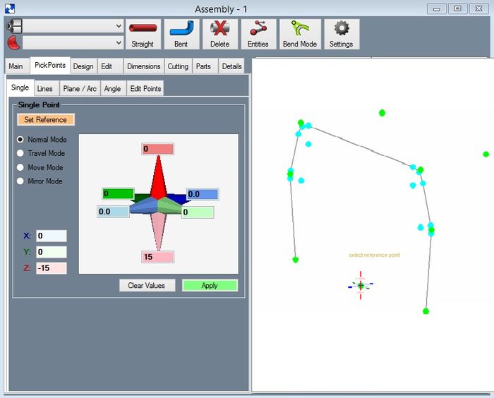
Step 1: I created two PickPoints coming off of my tangent points from the 1st hoop. Please note; the model is back-wards (front to back) compared to your picture.
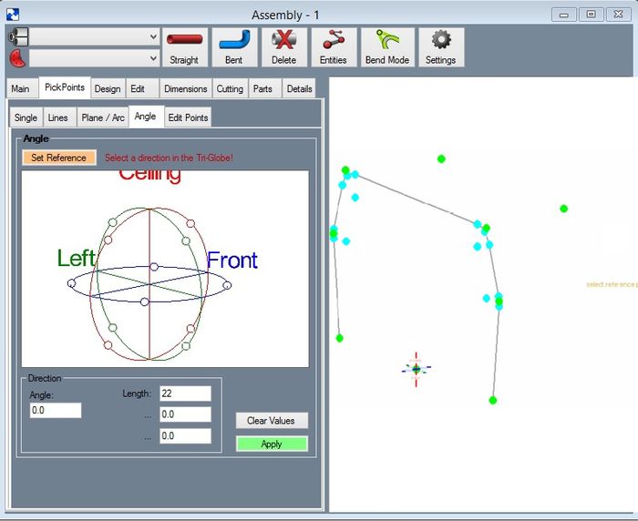
Step 2: I pretended I knew the angle down from the last two points created. This angle would be as if you layed a plate across the windshield of the vehicle. Don't worry about the "kick-out", just worry about the angle and the length of the plane between apexes. Use the "Angle" method for these. Repeat for both left and right side.
The "Angle" method works by selecting the point you are working off of, then select the correct "small" circle in the "Tri-Globe", enter in an angle [note the '90' degree numbers in the Tri-Globe, this give you a hint as to what is 0 vs. 90 degrees]. Now give it a length in the "Angle" tab.
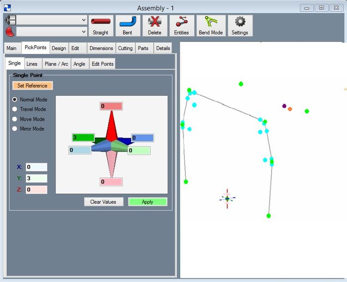
Step 3: Working off of the newest PickPoints (the points in the picture as orange) I placed 2 additional PickPoints kicked out each way [in my case 3 inches]. Use the "Single" method for these.
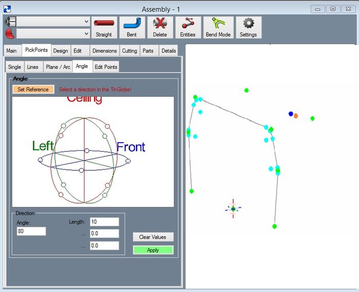
Step 4: Working off of the newest PickPoints (the points in the picture as dark blue) I went back to using the "Angle" method and placed and angle down of 80 degrees and a short distance. In this case the distance doesn't matter because I am just trying to create a line of direction.
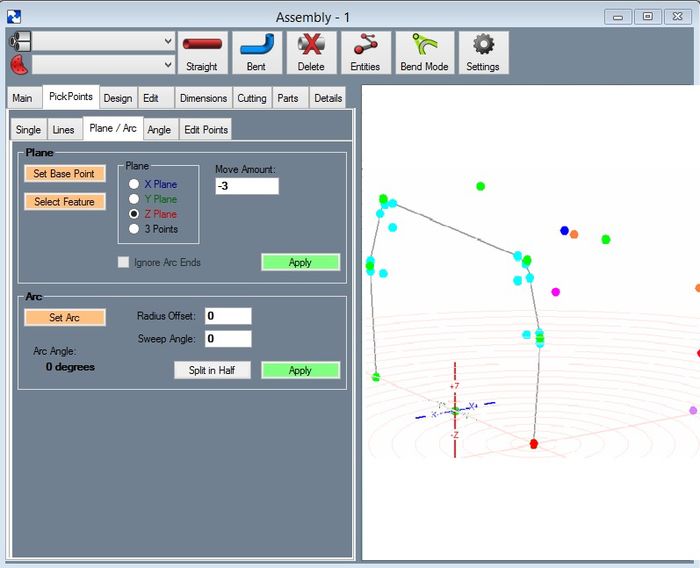
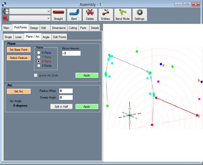
Step 5: After creating the last two PickPoints (the ones shown in the following picture as pink) I will use the "Plane" method. I know I want these PickPpoints to come down to the bottom of the car [if not, create a point x number of inches up or down and use that point to work off of]. Select the "Add PickPoint Plane" command button, Select the right hand lower side PickPoint of the 1st hoop [this is shown in the picture as the center of all of the circles], Now select the dark blue PickPoint and the pink PickPoint. The first pick creates the plane and the 2nd 2 picks create the line that is going to intersect the plane. Please find the magenta PickPoint in the picture, this is the point where the line and plane intersect each other. If this looks good, select the "Apply" command button to finalize the new PickPoint.
Repeat for both sides.
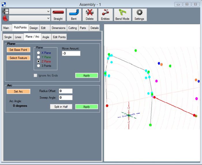
Step 6: I am going to assume for this illustration that the last 2 points we created are at the correct front/back location and at the correct ceiling/floor height, however, the are not at the correct left/right width. In my case I want to make them the same width as the 1st pillar. [again if the width is smaller or bigger, create PickPoints off of the 1st pillar left or right to locate the plane correctly.
I again selected the "Add PickPoint Plane" command button under the Plane method and select the same lower right corner of my 1st pillar. This time I changed the Plane direction to "Y Plane" [this is over on the left hand side of the tab]. Now select the last two points made as shown in the picture and "Apply" these points.
You will need to repeat on the far side as well.
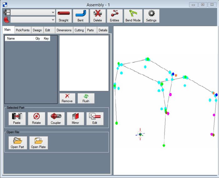
Step 7: Now play connect the dot by using the "Bent Part" command button on the "Main" tab.
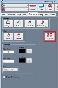
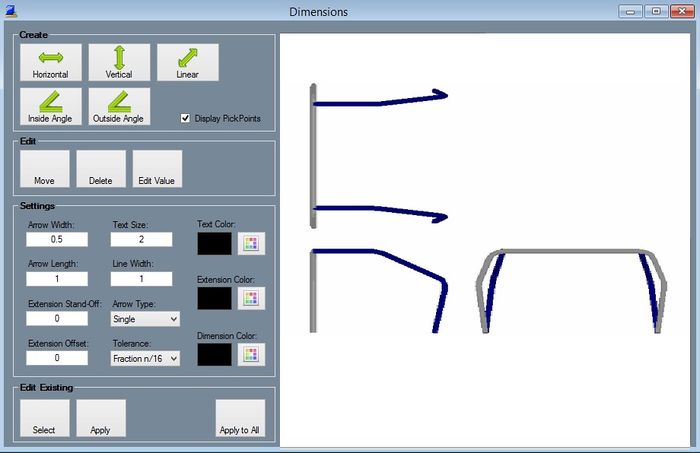
Here is a screen shot of it in the "Dimension Tab". To get to the "Dimension Tab" Click on the 2D Mode button. This shows you 3 views and you can get an idea how it is kicking to create your rotation.
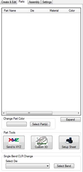
Step 8: Use the "Parts" tab and select the part from the list. Use the "Send to XYZ" command button to send it and find your cut length, bend locations, angles and rotations.
