Difference between revisions of "Cutting"
| (16 intermediate revisions by the same user not shown) | |||
| Line 1: | Line 1: | ||
| − | |||
| − | |||
| + | [[File:Cutting_picture12.png]] | ||
| − | The Cutting tab contains the tools necessary for adding cuts to the ends of parts. Wrappers can be printed which, when wrapped around the end of a tube, mark where the tube needs to be cut. | + | <h2>End Profiles</h2> |
| + | |||
| + | The End Profiles tab within the Cutting tab contains the tools necessary for adding cuts to the ends of parts. Wrappers can be printed which, when wrapped around the end of a tube, mark where the tube needs to be cut. | ||
| Line 24: | Line 25: | ||
[[File:auto-miter1.png]][[File:auto-miter2.png]][[File:auto-miter3.png]] | [[File:auto-miter1.png]][[File:auto-miter2.png]][[File:auto-miter3.png]] | ||
| + | <h3>Cutting Wrappers</h3> | ||
When viewing the details for the wrappers for a mitered cut, they should have these qualities. | When viewing the details for the wrappers for a mitered cut, they should have these qualities. | ||
| Line 53: | Line 55: | ||
Lastly, select the "'''Complete'''" [[File:Complete.png]] button and the new cut and information will show up on the left of the screen in the Cut Chart section. | Lastly, select the "'''Complete'''" [[File:Complete.png]] button and the new cut and information will show up on the left of the screen in the Cut Chart section. | ||
| + | |||
| + | <h3>Slot & Tab</h3> | ||
| + | |||
| + | '''RESERVED FOR DRAGON CUSTOMERS ONLY.''' | ||
| + | |||
| + | '''Use the Slot & Tab function only after you have set up your Slot & Tab settings in the [[Tube/Pipe Library]]. Attempting to use this function without creating valid settings applied to your tubing will not produce results.''' | ||
| + | |||
| + | *Click the Slot & Tab [[File:Ass_Slot_N_Tab1.png]] button after you've created a cut and click on the green highlighted tube to apply the tab to it. This will also apply the slot to the outer edge of the red highlighted tube. | ||
| + | |||
| + | *If the tab & slot is not wide or long enough, you can always change the settings in your [[Tube/Pipe Library]] and then click the '''"Complete"''' button to apply the changes to the cut. | ||
| + | |||
| + | [[File:Slot_Tab1_Example1.png]] | ||
<h3>Cut Settings</h3> | <h3>Cut Settings</h3> | ||
| − | If the '''Outside Diameter Only''' option is checked, the software will not display the inside diameter cut line for each cut. | + | If the '''Outside Diameter Only''' option is checked, the software will not display the inside diameter cut line for each cut. |
| + | Using a hole saw requires the checking of the outside of the material only.''' "Check"''' the option '''"Outside Diameter Only"'''. | ||
| + | |||
| + | [[File:HoleSaw3.jpg]] | ||
| + | |||
| + | Using a grinder or plasma cutter requires checking of both sides of the material. '''"Uncheck"''' the option '''"Outside Diameter Only"'''. | ||
| + | |||
| + | [[File:HoleSaw4.jpg]] | ||
| − | |||
| − | If | + | If '''Distance to Perp of Bend''' is checked, the red line will indicate the distance to the perpendicular of the bend. The cut wrapper's red line will display the distance to the tangent of the nearest bend combined with the outside radius of the bend. |
| − | If the ''' | + | If the '''Hide Completed Features''' option is checked, completed features from the new cut will be hidden in the design. |
| − | If ''' | + | If the '''Ignore Tube Ends''' option is checked, all new cuts will ignore the excess tubing leftover from all other cuts. |
| + | If '''Mitered Cut''' is checked, all new cuts will be calculated as straight mitered cuts. If you are using a hole saw to cut your tubes leave Mitered Cut unchecked. | ||
| + | |||
| + | If the '''Add Slot & Tab''' checkbox is checked, all new cuts will contain a tab on the intended cut tube and a slot on the adjoining tube. ''Adding a value into the value field to the right will rotate the tab around the tube by a degree between 0-360.'' | ||
<h3>Cut Chart</h3> | <h3>Cut Chart</h3> | ||
| − | [[File:cutting_2.png | + | [[File:cutting_2.png|600px]] |
| + | |||
A chart displaying a list of all the cuts currently applied to the assembly will be shown as well. | A chart displaying a list of all the cuts currently applied to the assembly will be shown as well. | ||
| Line 80: | Line 104: | ||
| − | [[File:cut_wrapper.png|400px | + | [[File:cut_wrapper.png|400px]] |
Click the '''Details''' button [[File:details.png]] to see a preview of the cutting wrapper. On each wrapper, there is a red line with a number on it. This line is used for lining up a wrapper on a tube. The number is the distance from the end of the tube that the red line should be. | Click the '''Details''' button [[File:details.png]] to see a preview of the cutting wrapper. On each wrapper, there is a red line with a number on it. This line is used for lining up a wrapper on a tube. The number is the distance from the end of the tube that the red line should be. | ||
| Line 94: | Line 118: | ||
*Rotation - The rotation of the holesaw plunge in relation to the closest bend (or opposite side of the tube in the case of a straight tube). | *Rotation - The rotation of the holesaw plunge in relation to the closest bend (or opposite side of the tube in the case of a straight tube). | ||
| + | |||
| + | |||
| + | <h2>Holes</h2> | ||
| + | |||
| + | '''RESERVED FOR DRAGON CUSTOMERS ONLY.''' | ||
| + | |||
| + | *'''Create Hole:''' To create a hole profile on a tube, click on the '''Create Hole''' [[File:Create_Hole_Tekla1.png]] button followed by the intended tube and click once more to indicate the location of the hole. | ||
| + | |||
| + | *'''Delete Hole:''' To delete a hole profile from a tube, click on the '''Delete Hole''' [[File:Delete_Hole_Tekla1.png]] button followed by the hole in the design. | ||
| + | |||
| + | <h3>Hole Shape</h3> | ||
| + | *The '''Hole Shape''' section is where you will designate the type/shape of the hole that will be inserted into the design. | ||
| + | |||
| + | [[File:Hole_Shape_Tekla1.png]] | ||
| + | |||
| + | '''Round:''' Select the '''Round''' [[File:Tekla_Hole_Round1.png]] option to create a round hole in the design. The size of this hole will be determined by the value you enter into the '''Width:''' value field in the '''Hole Dimensions''' section. | ||
| + | |||
| + | '''Square:''' Select the '''Square''' [[File:Tekla_Hole_Square1.png]] option to create a square hole in the design. The size of this hole will be determined by the values you enter into the '''Width:''' and '''Corner Radius:''' value fields in the '''Hole Dimensions''' section. | ||
| + | |||
| + | '''Rectangle:''' Select the '''Rectangle''' [[File:Tekla_Hole_Rectangle1.png]] option to create a rectangular hole in the design. The size of this hole will be determined by the values you enter into the '''Width:''', '''Height:''' and '''Corner Radius:''' value fields in the '''Hole Dimensions''' section. | ||
| + | |||
| + | '''Oval:''' Select the '''Oval''' [[File:Tekla_Hole_Oval1.png]] option to create a oval hole in the design. The size of this hole will be determined by the values you enter into the '''Width:''' and '''Height:''' value fields in the '''Hole Dimensions''' section. | ||
| + | |||
| + | '''Ellipse:''' Select the '''Ellipse''' [[File:Tekla_Hole_Ellipse1.png]] option to create a ellipse hole in the design. The size of this hole will be determined by the values you enter into the '''Width:''' and '''Height:''' value fields in the '''Hole Dimensions''' section. | ||
| + | |||
| + | '''Notch:''' Select the '''Notch''' [[File:Cutting_Hole_Notch1.png]] option to create a notch hole in the design. The gap size of this hole will be determined by the values you enter into the '''Bend Angle:''', '''Gap:''' and '''Corner Angle:''' values fields in the '''Notch Dimensions''' section. '''NOTE: This option will only be available when working with square or rectangle tubing.''' | ||
| + | |||
| + | <h3>Misc Check Box Options</h3> | ||
| + | |||
| + | *These miscellaneous options are where you can set physical attributes to the hole(s) your are placing in the design and choose whether or not the holes placed are tied to a point or placed freely. | ||
| + | |||
| + | [[File:Misc_Holes_Options_Tekla1.png]] | ||
| + | |||
| + | '''Free-Select Mode:''' Check the '''Free-Select Mode''' [[File:Free_Select_Mode_Tekla1.png]] check box and you will be able to place your hole exactly where you click your cursor. | ||
| + | |||
| + | '''Perpendicular Plunge:''' Check the '''Perpendicular Plunge''' [[File:Perpendicular_Plunge_Tekla1.png]] check box and you will be able to place your hole at a 90 degree perpendicular orientation to the tubing. If this box is unchecked, you will have the option to click a point after the hole has been placed to indicate the angle and direction of the plunge. | ||
| + | |||
| + | '''Create Both Holes:''' Check the '''Create Both Holes''' [[File:Create_Both_Holes_Tekla1.png]] check box and holes will be placed on both sides of the tubing when a hole is placed. | ||
| + | |||
| + | <h3>Hole Dimensions</h3> | ||
| + | *The '''Hole Dimensions''' section is where you will enter the dimension values for the hole you have selected before you place it in the design. | ||
| + | |||
| + | [[File:Hole_Dimensions_Section_Tekla1.png]] | ||
| + | |||
| + | <h3>Reference Points (Dragon)</h3> | ||
| + | [[File:Reference_Points_Dragon1.png]] | ||
| + | |||
| + | *'''Create Point:''' Click the '''Create Point''' [[File:Ass_Create_Reference_Point1.png]] button followed by the intended tube in the design, then click on a location on the tube to place a reference point. ''This will be available in the Dragon software as a reference point.'' | ||
| + | |||
| + | *'''Delete Point:''' Click the '''Delete Point''' [[File:Ass_Delete_Point2.png]] button followed by a point in the design to delete it from the tube. | ||
Latest revision as of 14:02, 7 February 2018
Contents
End Profiles
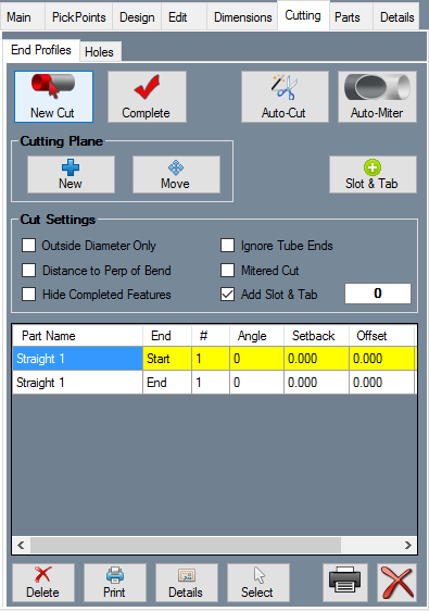
The End Profiles tab within the Cutting tab contains the tools necessary for adding cuts to the ends of parts. Wrappers can be printed which, when wrapped around the end of a tube, mark where the tube needs to be cut.
Make Cuts
Click the "New Cut" ![]() button and click a part. The cut part will be highlighted in green once selected. Click a second part, plane, or multiple parts that the first part will be cut to fit against. The second and any consecutive selected parts will be highlighted in red. Click the "Complete"
button and click a part. The cut part will be highlighted in green once selected. Click a second part, plane, or multiple parts that the first part will be cut to fit against. The second and any consecutive selected parts will be highlighted in red. Click the "Complete" ![]() button. The cut should appear in the list of cuts on the Cutting tab and shown on the assembly.
button. The cut should appear in the list of cuts on the Cutting tab and shown on the assembly.
Click the "Auto-Cut" ![]() button to let the software attempt to generate all cuts in the assembly project.
button to let the software attempt to generate all cuts in the assembly project.
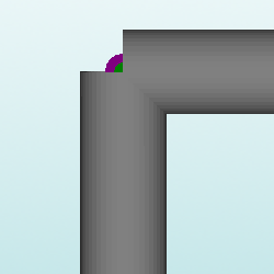
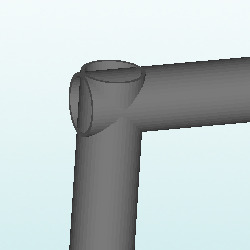
Click the "Auto-Miter" ![]() button to extend the lengths of intersecting tubes past their center line so they can be cut equally.
button to extend the lengths of intersecting tubes past their center line so they can be cut equally.
Cutting Wrappers
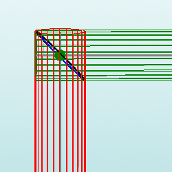
When viewing the details for the wrappers for a mitered cut, they should have these qualities.
Cutting Plane
Using the "Cutting Plane" function to cut a section of tube is different from cutting tubes that intersect. This tool is used for cutting a specific place on a bend or straight tube that does not intersect another tube.
Using the cutting plane feature, a custom plane can be defined and used to place cuts anywhere on the assembly design.
To place a cutting plane, click the "New" ![]() button under the "Cutting" tab and click on a PickPoint to define the center/base point of the plane. Then click the first and second direction of the plane.
button under the "Cutting" tab and click on a PickPoint to define the center/base point of the plane. Then click the first and second direction of the plane.
Once a plane is place in the assembly, it can be used as a cutting feature and will allow straight cuts to be placed anywhere.
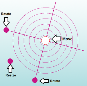
To move the plane, click the "Move" ![]() button. Then click and drag the move tools directly on the plane to move, resize, and rotate the plane. See image below.
button. Then click and drag the move tools directly on the plane to move, resize, and rotate the plane. See image below.
Once the cutting plane in in the correct position, the user can record a cut by selecting the "New Cut" ![]() button.
button.
Then, select the tube that you are trying to cut, followed by the cutting plane itself. If you've done everything right, the cutting plane will be highlighted when you place your cursor over it.
Lastly, select the "Complete" ![]() button and the new cut and information will show up on the left of the screen in the Cut Chart section.
button and the new cut and information will show up on the left of the screen in the Cut Chart section.
Slot & Tab
RESERVED FOR DRAGON CUSTOMERS ONLY.
Use the Slot & Tab function only after you have set up your Slot & Tab settings in the Tube/Pipe Library. Attempting to use this function without creating valid settings applied to your tubing will not produce results.
- Click the Slot & Tab
 button after you've created a cut and click on the green highlighted tube to apply the tab to it. This will also apply the slot to the outer edge of the red highlighted tube.
- If the tab & slot is not wide or long enough, you can always change the settings in your Tube/Pipe Library and then click the "Complete" button to apply the changes to the cut.
Cut Settings
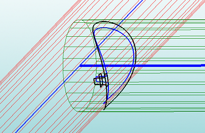
If the Outside Diameter Only option is checked, the software will not display the inside diameter cut line for each cut. Using a hole saw requires the checking of the outside of the material only. "Check" the option "Outside Diameter Only".
Using a grinder or plasma cutter requires checking of both sides of the material. "Uncheck" the option "Outside Diameter Only".
If Distance to Perp of Bend is checked, the red line will indicate the distance to the perpendicular of the bend. The cut wrapper's red line will display the distance to the tangent of the nearest bend combined with the outside radius of the bend.
If the Hide Completed Features option is checked, completed features from the new cut will be hidden in the design.
If the Ignore Tube Ends option is checked, all new cuts will ignore the excess tubing leftover from all other cuts.
If Mitered Cut is checked, all new cuts will be calculated as straight mitered cuts. If you are using a hole saw to cut your tubes leave Mitered Cut unchecked.
If the Add Slot & Tab checkbox is checked, all new cuts will contain a tab on the intended cut tube and a slot on the adjoining tube. Adding a value into the value field to the right will rotate the tab around the tube by a degree between 0-360.
Cut Chart
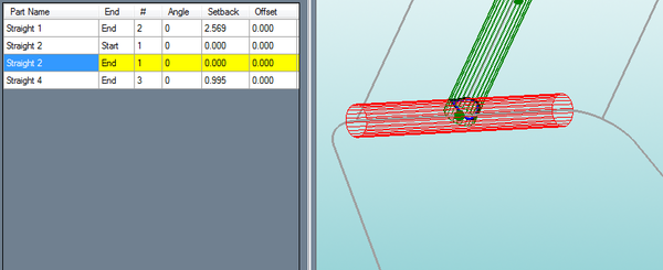
A chart displaying a list of all the cuts currently applied to the assembly will be shown as well.
Click on a cut to see a preview of the cut on the 3D model of the assembly.
Click Delete ![]() to remove the cut from the tube, or click Delete All
to remove the cut from the tube, or click Delete All ![]() to remove all cuts from the Assembly project.
to remove all cuts from the Assembly project.
Click Print ![]() to print the currently selected wrapper, or click Print All
to print the currently selected wrapper, or click Print All ![]() to print out all wrappers for the entire Assembly project.
to print out all wrappers for the entire Assembly project.
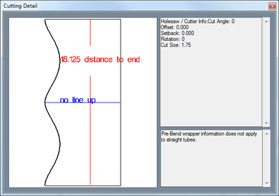 Click the Details button
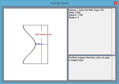
 ![]() to see a preview of the cutting wrapper. On each wrapper, there is a red line with a number on it. This line is used for lining up a wrapper on a tube. The number is the distance from the end of the tube that the red line should be.
to see a preview of the cutting wrapper. On each wrapper, there is a red line with a number on it. This line is used for lining up a wrapper on a tube. The number is the distance from the end of the tube that the red line should be.
Click the Select button ![]() and click on a cut in the display area to select it from the assembly directly.
and click on a cut in the display area to select it from the assembly directly.
Cutting Definitions
- Setback - Distance from the end of the tube to the centerline of the cross tube. This point is the intersection of the cross tube (centerline) and the centerline of the cut tube.
- Offset - The up/down distance from the centerline of the cut tube to the centerline of the cross tube when looking at the face of the cut.
- Angle - The plunge angle of the holesaw. A zero degree angle would be a plunge at a perpendicular (90 degree) angle to the cut tube.
- Rotation - The rotation of the holesaw plunge in relation to the closest bend (or opposite side of the tube in the case of a straight tube).
Holes
RESERVED FOR DRAGON CUSTOMERS ONLY.
- Create Hole: To create a hole profile on a tube, click on the Create Hole
 button followed by the intended tube and click once more to indicate the location of the hole.
- Delete Hole: To delete a hole profile from a tube, click on the Delete Hole
 button followed by the hole in the design.
Hole Shape
- The Hole Shape section is where you will designate the type/shape of the hole that will be inserted into the design.
Round: Select the Round ![]() option to create a round hole in the design. The size of this hole will be determined by the value you enter into the Width: value field in the Hole Dimensions section.
option to create a round hole in the design. The size of this hole will be determined by the value you enter into the Width: value field in the Hole Dimensions section.
Square: Select the Square ![]() option to create a square hole in the design. The size of this hole will be determined by the values you enter into the Width: and Corner Radius: value fields in the Hole Dimensions section.
option to create a square hole in the design. The size of this hole will be determined by the values you enter into the Width: and Corner Radius: value fields in the Hole Dimensions section.
Rectangle: Select the Rectangle ![]() option to create a rectangular hole in the design. The size of this hole will be determined by the values you enter into the Width:, Height: and Corner Radius: value fields in the Hole Dimensions section.
option to create a rectangular hole in the design. The size of this hole will be determined by the values you enter into the Width:, Height: and Corner Radius: value fields in the Hole Dimensions section.
Oval: Select the Oval ![]() option to create a oval hole in the design. The size of this hole will be determined by the values you enter into the Width: and Height: value fields in the Hole Dimensions section.
option to create a oval hole in the design. The size of this hole will be determined by the values you enter into the Width: and Height: value fields in the Hole Dimensions section.
Ellipse: Select the Ellipse ![]() option to create a ellipse hole in the design. The size of this hole will be determined by the values you enter into the Width: and Height: value fields in the Hole Dimensions section.
option to create a ellipse hole in the design. The size of this hole will be determined by the values you enter into the Width: and Height: value fields in the Hole Dimensions section.
Notch: Select the Notch ![]() option to create a notch hole in the design. The gap size of this hole will be determined by the values you enter into the Bend Angle:, Gap: and Corner Angle: values fields in the Notch Dimensions section. NOTE: This option will only be available when working with square or rectangle tubing.
option to create a notch hole in the design. The gap size of this hole will be determined by the values you enter into the Bend Angle:, Gap: and Corner Angle: values fields in the Notch Dimensions section. NOTE: This option will only be available when working with square or rectangle tubing.
Misc Check Box Options
- These miscellaneous options are where you can set physical attributes to the hole(s) your are placing in the design and choose whether or not the holes placed are tied to a point or placed freely.
Free-Select Mode: Check the Free-Select Mode ![]() check box and you will be able to place your hole exactly where you click your cursor.
check box and you will be able to place your hole exactly where you click your cursor.
Perpendicular Plunge: Check the Perpendicular Plunge ![]() check box and you will be able to place your hole at a 90 degree perpendicular orientation to the tubing. If this box is unchecked, you will have the option to click a point after the hole has been placed to indicate the angle and direction of the plunge.
check box and you will be able to place your hole at a 90 degree perpendicular orientation to the tubing. If this box is unchecked, you will have the option to click a point after the hole has been placed to indicate the angle and direction of the plunge.
Create Both Holes: Check the Create Both Holes ![]() check box and holes will be placed on both sides of the tubing when a hole is placed.
check box and holes will be placed on both sides of the tubing when a hole is placed.
Hole Dimensions
- The Hole Dimensions section is where you will enter the dimension values for the hole you have selected before you place it in the design.
