Difference between revisions of "Cutting the End of a Straight Tube"
(Created page with "A straight part is a part defined without a bend. Following are the steps to setting up the cutting for a straight part. Step 1) Select the "Cutting" tab. Step 2) Select th...") |
|||
| (3 intermediate revisions by the same user not shown) | |||
| Line 3: | Line 3: | ||
Following are the steps to setting up the cutting for a straight part. | Following are the steps to setting up the cutting for a straight part. | ||
| − | Step 1 | + | '''Step 1:''' Select the '''"Cutting"''' tab. |
| − | Step 2 | + | '''Step 2:''' Select the '''"New Cut"''' command button. |
| − | Step 3 | + | '''Step 3:''' Select the tube you are going to cut. Note: The straight parts have 2 red dots on each part. You need select the red dot closest to the end you are going to cut. You will find our part turn green in color. |
| − | CutEndStraight1. | + | [[File:CutEndStraight1.jpg]] |
| − | Step 4 | + | '''Step 4:''' Select the dot(s) representing the tube section(s) that our part is going to be cut to. You will find the intersecting tubes will turn red. |
| − | CutEndStraight2. | + | [[File:CutEndStraight2.jpg]] |
| − | Step 5 | + | '''Step 5:''' Select the '''"Cut Complete"''' command button. |
| − | CutEndStraight3. | + | [[File:CutEndStraight3.jpg]] |
Notice the intersection now has a black and a blue cut marks showing the inside and outside of the material where each meets the intersection part(s). | Notice the intersection now has a black and a blue cut marks showing the inside and outside of the material where each meets the intersection part(s). | ||
| − | Step 6 | + | '''Step 6:''' Select the '''"Print"''' command button. |
| − | CutEndStraight4. | + | [[File:CutEndStraight4.jpg]] |
The cutting templates can be called up at a later time by selecting them from the list shown. | The cutting templates can be called up at a later time by selecting them from the list shown. | ||
| − | NOTE: If you desire a cut wrapper for both ends of a single straight tube, print out the wrappers AFTER both cuts have been defined. This will allow for proper rotational calibration (blue lines) and proper distance between the wrappers calibration (red calibration lines). | + | '''NOTE: If you desire a cut wrapper for both ends of a single straight tube, print out the wrappers AFTER both cuts have been defined.''' This will allow for proper rotational calibration (blue lines) and proper distance between the wrappers calibration (red calibration lines). |
Latest revision as of 14:13, 5 October 2015
A straight part is a part defined without a bend.
Following are the steps to setting up the cutting for a straight part.
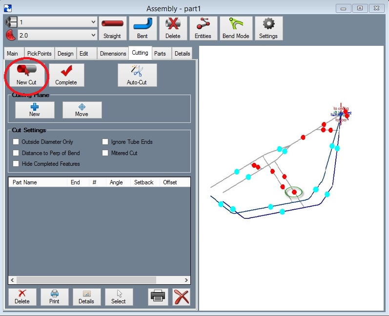
Step 1: Select the "Cutting" tab.
Step 2: Select the "New Cut" command button.
Step 3: Select the tube you are going to cut. Note: The straight parts have 2 red dots on each part. You need select the red dot closest to the end you are going to cut. You will find our part turn green in color.
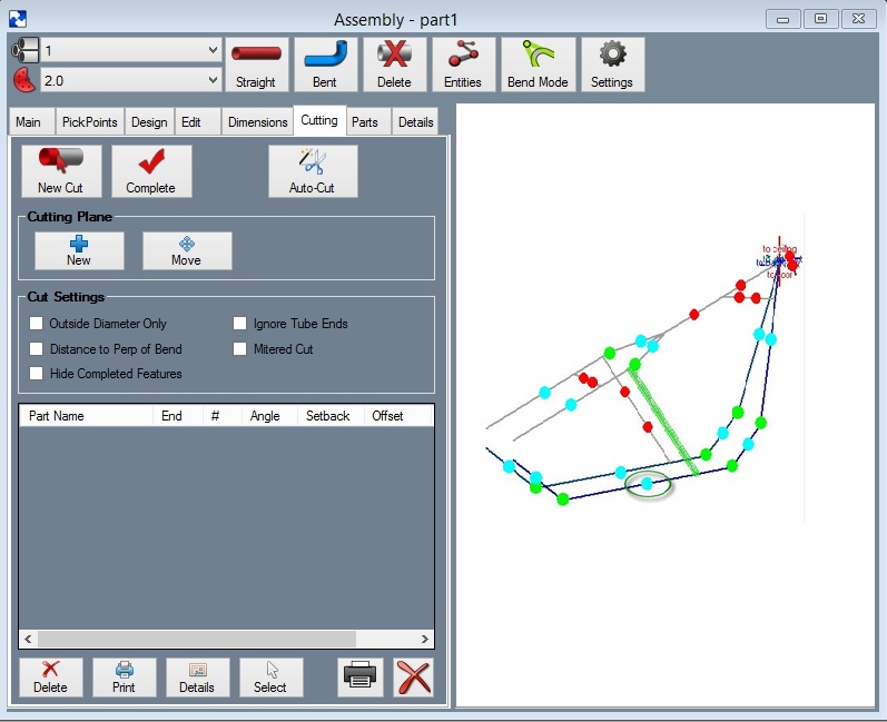
Step 4: Select the dot(s) representing the tube section(s) that our part is going to be cut to. You will find the intersecting tubes will turn red.
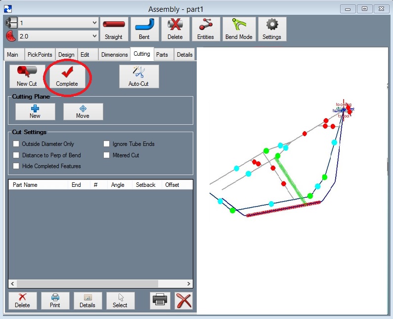
Step 5: Select the "Cut Complete" command button.
Notice the intersection now has a black and a blue cut marks showing the inside and outside of the material where each meets the intersection part(s).
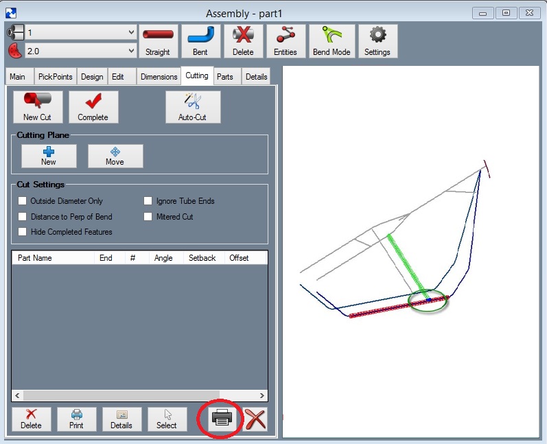
Step 6: Select the "Print" command button.
The cutting templates can be called up at a later time by selecting them from the list shown.
NOTE: If you desire a cut wrapper for both ends of a single straight tube, print out the wrappers AFTER both cuts have been defined. This will allow for proper rotational calibration (blue lines) and proper distance between the wrappers calibration (red calibration lines).


