Difference between revisions of "Dragon Rotation Calibration"
| (One intermediate revision by the same user not shown) | |||
| Line 1: | Line 1: | ||
| − | '''"This guide will help you understand all of the processes and procedures involved in calibrating your rotational settings within your Dragon Software to create precision | + | '''"This guide will help you understand all of the processes and procedures involved in calibrating your rotational settings within your Dragon Software to create precision bend marks with your machine as they pertain to the rotational position they will be placed around the circumference of your tubing."''' |
| + | |||
| + | '''In the rare case shown below, the rotational offset value would be set to '0', but in most cases the value is going to either by '90' if the tubing is being bent counter-clockwise, or '270' if the tubing is being bent clockwise. That is why this rotational wizard is important.''' | ||
| + | |||
| + | [[File:Rotation_Die_N_Tube1.png]] | ||
=Rotation Calibration Wizard Setup= | =Rotation Calibration Wizard Setup= | ||
Latest revision as of 12:33, 24 March 2017
"This guide will help you understand all of the processes and procedures involved in calibrating your rotational settings within your Dragon Software to create precision bend marks with your machine as they pertain to the rotational position they will be placed around the circumference of your tubing."
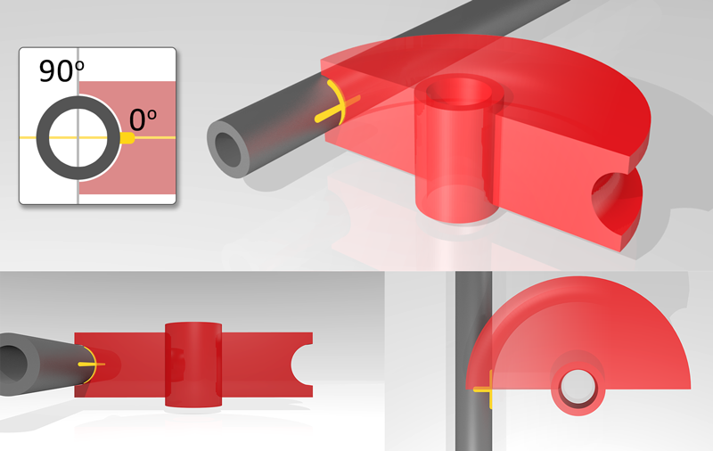
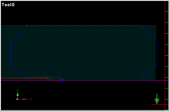
In the rare case shown below, the rotational offset value would be set to '0', but in most cases the value is going to either by '90' if the tubing is being bent counter-clockwise, or '270' if the tubing is being bent clockwise. That is why this rotational wizard is important.
Contents
Rotation Calibration Wizard Setup
- In order to start the process of calibrating your rotational settings, begin by selecting your "Die Library"
 from the Dragon "Task Menu Screen".
- Select the die that you plan to calibrate from the die list to the left, then switch to the Bend Marks
 tab.
tab.
Select Die and Material
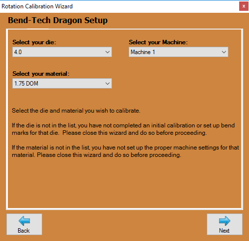
- Now, select the die you're using along with the associated material that will be used in this calibration. If there are no dies or materials available from the lists, you may need to do a die Calibration and enter your material into the Tube/Pipe Library before continuing.
Select Bender
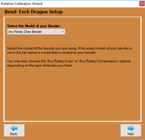
- On this page, select the model of bender that you're using. If it is not available from the list, please select Any Rotary Draw, Any Rotary Compression or Center Compression bender options. If you need to see which style bender you own, see the Dimension Location page for more help.
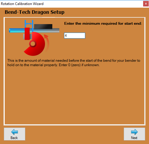
Minimum for Start End
- Here, enter the minimum distance needed before the start of the bend in order for the bender to hold onto the material during bending.
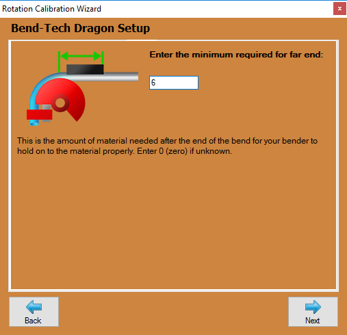
Minimum for Far End
- Here, enter the minimum distance needed after the bend in order to hold onto the material during bending.
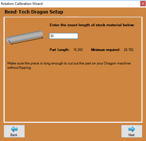
Exact Cut Length
- Now, type in the exact cut length being used for this calibration process. This must be longer than the Minimum required as shown on this screen.
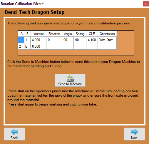
Send to Machine
- On this page, your bending instructions for this 90 degree part will be shown and you will be prompted to send this pat information to the Dragon machine for cutting and marking. Click on the Send to Machine button and Mach 3 will open. Then, press the Start button on the control panel and the machine will move into the loading position. Proceed to loading the material, tighten the jaws of the chuck and ensure the front gate is closed around the material. Then, press start again to begin marking and cutting.
Bend to 90 Degrees
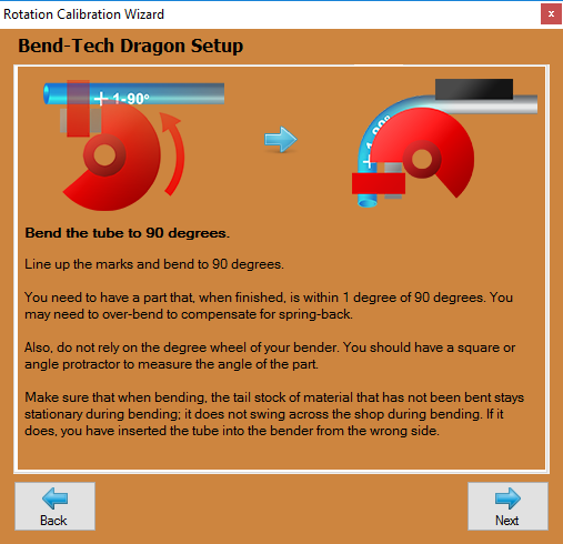
- In this step, line up the tube in your bender based on the Dragon's mark and bend it to a 90 degree angle. This must be within 1 degree of 90 degrees so you must take your material's spring back into account as well. Be sure to read the instructions to make sure you've loaded the right end of the tubing into the bender.
Measure the Rotation
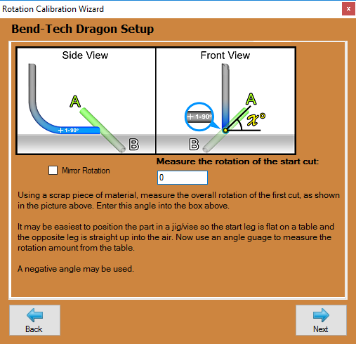
- Here, you will have to use an angle gauge and measure the rotation of the start cut in order to determine your rotational offset. Check the Mirror Rotation check box if the image does not match your results.
Verify
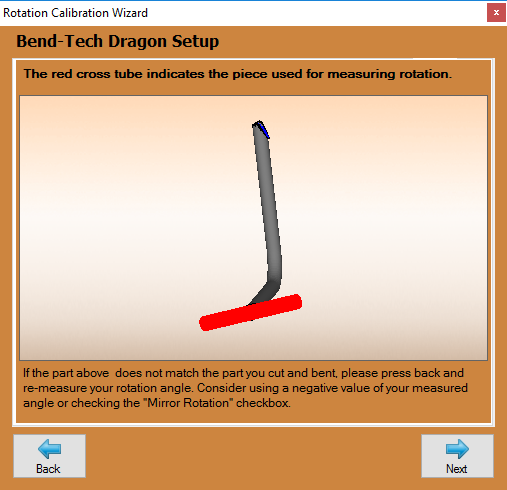
- Here, the 3D display will show the model you have created by following the instructions of this guide. If the 3D display shows different than what you've fabricated, press the Back button and re-do the previous step. If it appears to be the same, click Next to continue.
Calibration Complete
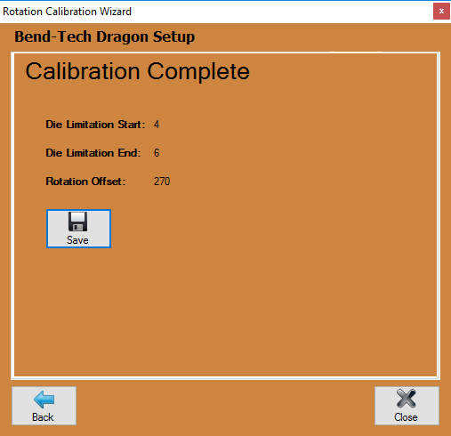
- Now, the rotation calibration process is complete. You will be given a Rotation Offset value and the option to Save this information into the settings for this die and material set. Click the Close button after you save.
