Difference between revisions of "Dragon Diamond Notch Bridging Tutorial"
| (8 intermediate revisions by the same user not shown) | |||
| Line 63: | Line 63: | ||
'''9.''' A window will appear asking if you'd like to indicate a rotational value for the part itself. Leave this value at '''0''' and click the '''OK''' button. Your part should now appear as a '''line''' in the display screen. | '''9.''' A window will appear asking if you'd like to indicate a rotational value for the part itself. Leave this value at '''0''' and click the '''OK''' button. Your part should now appear as a '''line''' in the display screen. | ||
| − | |||
| − | |||
| Line 70: | Line 68: | ||
| − | ''' | + | '''10.''' To view your straight part as a 3D rendering, click on the '''Display''' button from above. |
[[File:DNB12.png]] | [[File:DNB12.png]] | ||
| + | |||
| + | |||
| + | '''11.''' Then, click on the '''Cutting''' tab to access the options to create cuts and holes on your part. | ||
| + | |||
[[File:DNB13.png]] | [[File:DNB13.png]] | ||
| + | |||
| + | |||
| + | '''12.''' Select the '''Holes''' sub tab to access the options for making holes only. | ||
| + | |||
[[File:DNB14.png]] | [[File:DNB14.png]] | ||
| + | |||
| + | |||
| + | '''13.''' Under the '''Hole Type''' section, select the '''Notch''' option. ''NOTE: This is only available as a hole type for square or rectangular tubing.'' | ||
| + | |||
[[File:DNB15.png]] | [[File:DNB15.png]] | ||
| + | |||
| + | |||
| + | '''14.''' Under the '''Creation Method''' select the '''Values''' option. This indicates that the holes will be created based on the value you assign it. ''(Other creation methods include Pickpoints - in which 3 pickpoints are necessary for hole placement, Free Select - in which the hole will be placed wherever the user clicks in the design, and Cross Tube - in which case the user will need a intersecting tube created in the design and will first click the tube that will receive the notch followed by the FAR END of the cross tube intersecting it in order to place the hole.)'' | ||
| + | |||
[[File:DNB16.png]] | [[File:DNB16.png]] | ||
| + | |||
| + | |||
| + | '''15.''' Next, type '''6''' into the '''Distance''' field to the right of the creation method section. This indicates that our notch center will be located 6 inches from the start of tube. ''The start of tube is assigned according to the first Pickpoint that was selected during the drawing process.'' | ||
| + | |||
[[File:DNB17.png]] | [[File:DNB17.png]] | ||
| + | |||
| + | |||
| + | '''16.''' Leave all of the specific '''Notch Dimensions''' as they are and click on the '''Create Hole''' button at the top of this section. | ||
| + | |||
| + | |||
| + | [[File:DNB18.png]][[File:DNB19.png]] | ||
| + | |||
| + | |||
| + | '''17.''' Now, click on the tube in the display screen followed by the '''Apply''' button to place the notch on our part. | ||
| + | |||
| + | |||
| + | [[File:DNB20.png]] | ||
| + | |||
| + | |||
| + | '''18.''' After checking the 3D display using the '''Display''' button from above, your part should appear like the image below. | ||
| + | |||
| + | |||
| + | [[File:DNB21.png]] | ||
| + | |||
| + | |||
| + | '''19.''' Now, to transfer this part to the Dragon CAM software and prepare for a diamond bridge, click on the '''Transfer''' drop down menu from the top of the screen and select the '''Dragon CAM''' option. | ||
| + | |||
| + | |||
| + | [[File:DNB22.png]] | ||
| + | |||
| + | |||
| + | '''20.''' The Dragon CAM software should open if it isn't already (or if it is, you will have to reveal the screen from your computer's task menu - typically below) and the '''Part Transfer''' window will be open. You will want to ensure that you have the same/similar material selected from the drop down menu here and select the '''Designer''' button from below to send this to the Edit Flat/Designer interface. | ||
| + | |||
| + | ''NOTE: If you do not have this material set up in the Dragon CAM side of the software, this material will need to be added to the Tube/Pipe Library as instructed in your Setup Checklist - Emailed to each Dragon user.'' | ||
| + | |||
| + | |||
| + | [[File:DNB23.png]] | ||
| + | |||
| + | |||
| + | '''21.''' With the part sent to the Designer interface (also known as Edit Flat), you will '''Maximize''' the screen and select the '''Actions''' tab to the far right. | ||
| + | |||
| + | |||
| + | [[File:DNB24.png]] | ||
| + | |||
| + | [[File:DNB25.png]] | ||
| + | |||
| + | |||
| + | '''22.''' Then, select the '''Cutting''' button followed by the '''Diamond Tabs''' button. | ||
| + | |||
| + | |||
| + | [[File:DNB26.png]] | ||
| + | |||
| + | |||
| + | '''23.''' Lastly, leave the notch dimensions as they are and select the center of your notch to place the bridging option as shown below. | ||
| + | |||
| + | |||
| + | [[File:DNB27.png]] | ||
| + | |||
| + | |||
| + | '''24.''' Now that the part is finished, you are free to adjust/edit any other geometry in this interface, or to send this part to the nesting interface using the '''Nest Part''' button located at the top of the screen. | ||
| + | |||
| + | |||
| + | [[File:DNB28.png]] | ||
| + | |||
| + | |||
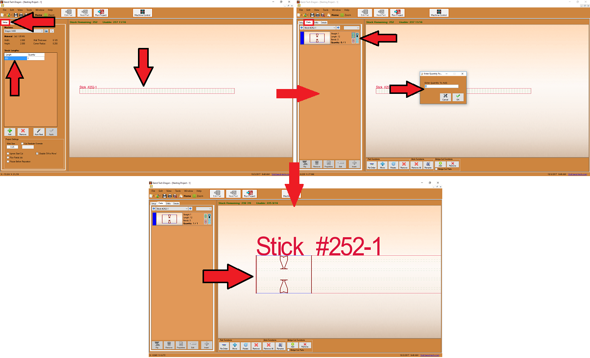
| + | '''25.''' Here, you can designate the stock length of your tubing in the '''Setup''' tab, add your part to the stock length in the '''Parts''' tab, and view the machine order of actions in the '''Shifts''' tab. | ||
| + | |||
| + | |||
| + | [[File:DNB29.png]] | ||
| + | |||
| + | |||
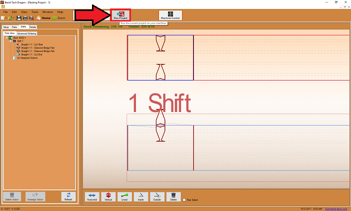
| + | '''26.''' Finally, you can send the job to the machine by selecting the '''Run Project''' button at the top of the screen. | ||
| + | |||
| + | |||
| + | [[File:DNB30.png]] | ||
Latest revision as of 09:35, 4 October 2017
Dragon Diamond Notch Bridging Tutorial
Things To Know
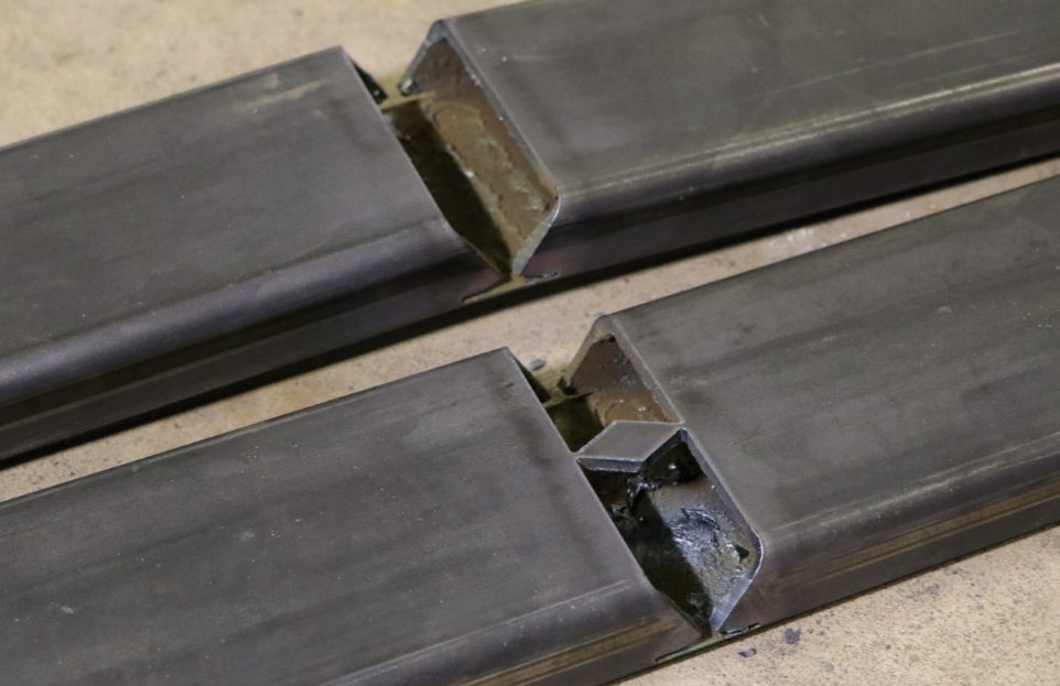
- This tutorial will step you through the process of creating a straight design in Bend-Tech Dragon CAD, add a notch cutout and show you where to take it next in order to add a notch bridge . As you walk through this tutorial, procedures are designed based on your knowledge of earlier procedures. Because of this, it is very important that you carefully step through this guide, understanding everything along the way.
Tutorial
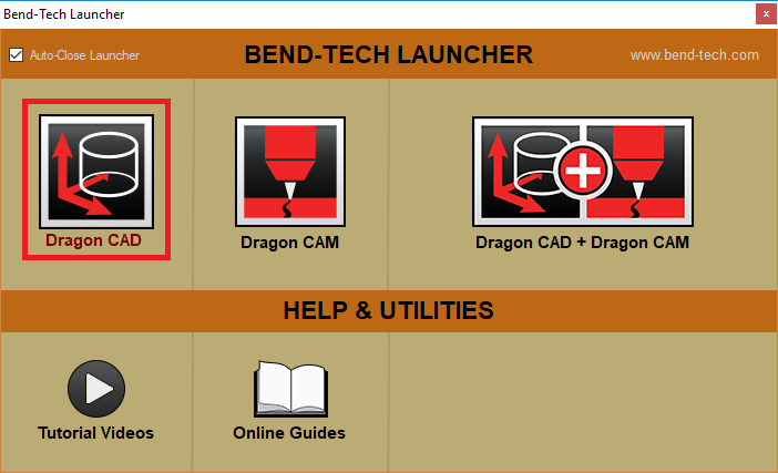
1. Start by opening up the Bend-Tech Launcher on your computer and select the Dragon CAD option so we can start our design process.
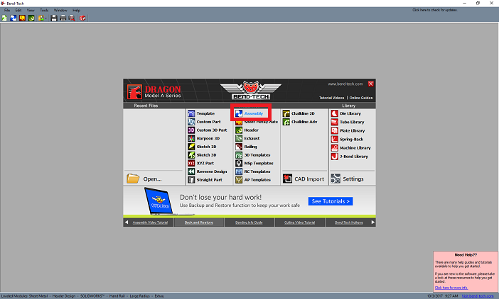
2. With the Task Menu screen open, select the Assembly designer option to begin drawing our part.
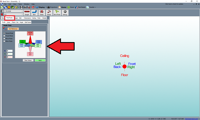
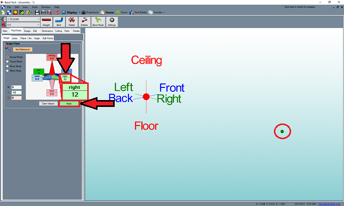
3. Maximize the screen here and select the Pickpoints tab. We will now create a single Pickpoint to indicate the length of a single part.
4. Select the Right entry field and type 12 into it to indicate a 12 inch part.
5. Click the Apply button to apply the point in the design.
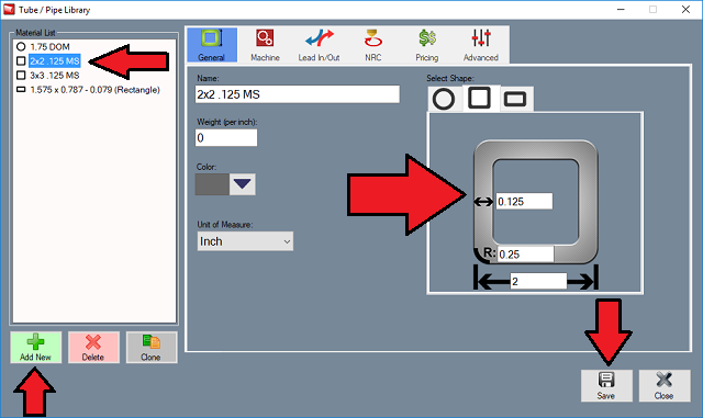
6. Select a Square OR Rectangular material from the material drop down list (the size of which is irrelevant). If you have not created one, you must first create one in the Tube/Pipe Library beforehand. This is available in the TOOLS tab at the top of your screen.
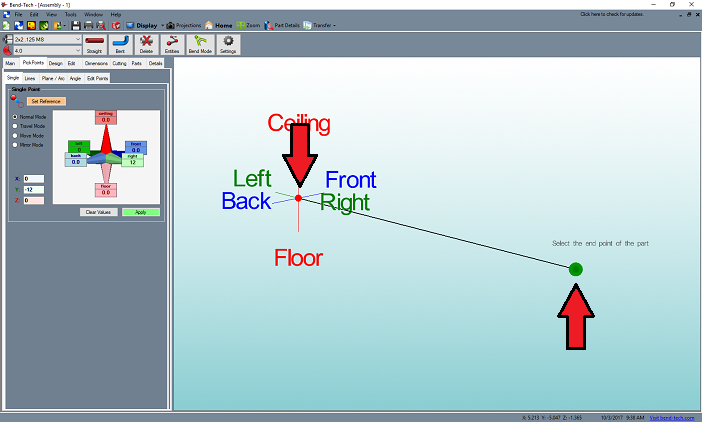
7. Once you have a square or rectangular material selected, click on the Straight button next to the material and die selection menus to indicate that we are drawing a straight part.
8. Then, click on the Tri-star in the display screen followed by our user-created point to draw our straight part.
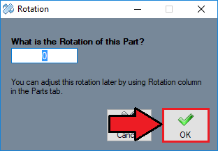
9. A window will appear asking if you'd like to indicate a rotational value for the part itself. Leave this value at 0 and click the OK button. Your part should now appear as a line in the display screen.
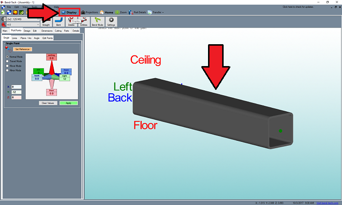
10. To view your straight part as a 3D rendering, click on the Display button from above.
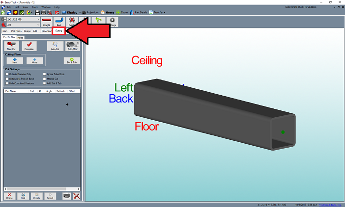
11. Then, click on the Cutting tab to access the options to create cuts and holes on your part.
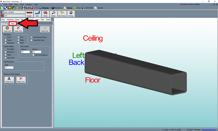
12. Select the Holes sub tab to access the options for making holes only.
13. Under the Hole Type section, select the Notch option. NOTE: This is only available as a hole type for square or rectangular tubing.
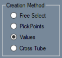
14. Under the Creation Method select the Values option. This indicates that the holes will be created based on the value you assign it. (Other creation methods include Pickpoints - in which 3 pickpoints are necessary for hole placement, Free Select - in which the hole will be placed wherever the user clicks in the design, and Cross Tube - in which case the user will need a intersecting tube created in the design and will first click the tube that will receive the notch followed by the FAR END of the cross tube intersecting it in order to place the hole.)
15. Next, type 6 into the Distance field to the right of the creation method section. This indicates that our notch center will be located 6 inches from the start of tube. The start of tube is assigned according to the first Pickpoint that was selected during the drawing process.
16. Leave all of the specific Notch Dimensions as they are and click on the Create Hole button at the top of this section.
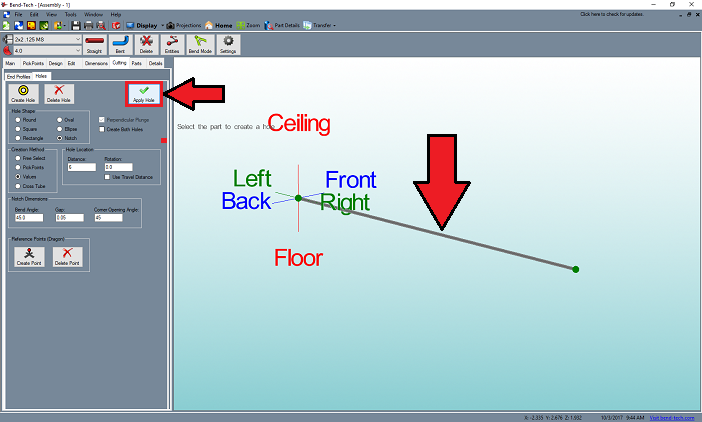
17. Now, click on the tube in the display screen followed by the Apply button to place the notch on our part.
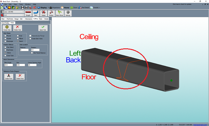
18. After checking the 3D display using the Display button from above, your part should appear like the image below.
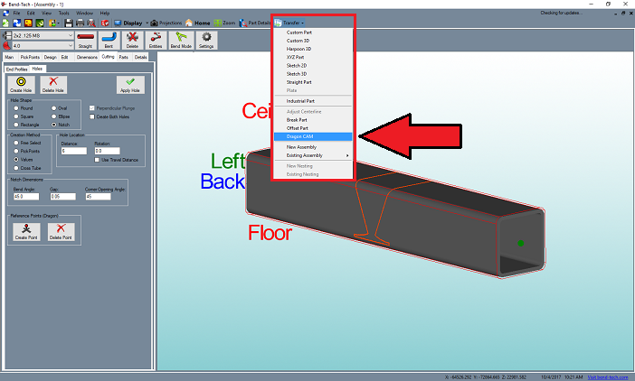
19. Now, to transfer this part to the Dragon CAM software and prepare for a diamond bridge, click on the Transfer drop down menu from the top of the screen and select the Dragon CAM option.
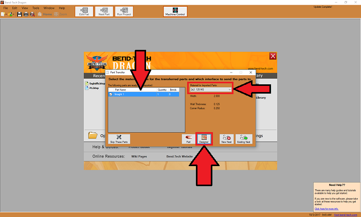
20. The Dragon CAM software should open if it isn't already (or if it is, you will have to reveal the screen from your computer's task menu - typically below) and the Part Transfer window will be open. You will want to ensure that you have the same/similar material selected from the drop down menu here and select the Designer button from below to send this to the Edit Flat/Designer interface.
NOTE: If you do not have this material set up in the Dragon CAM side of the software, this material will need to be added to the Tube/Pipe Library as instructed in your Setup Checklist - Emailed to each Dragon user.
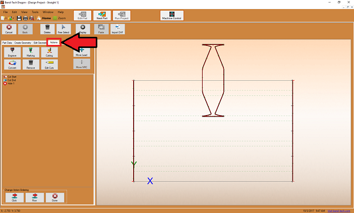
21. With the part sent to the Designer interface (also known as Edit Flat), you will Maximize the screen and select the Actions tab to the far right.
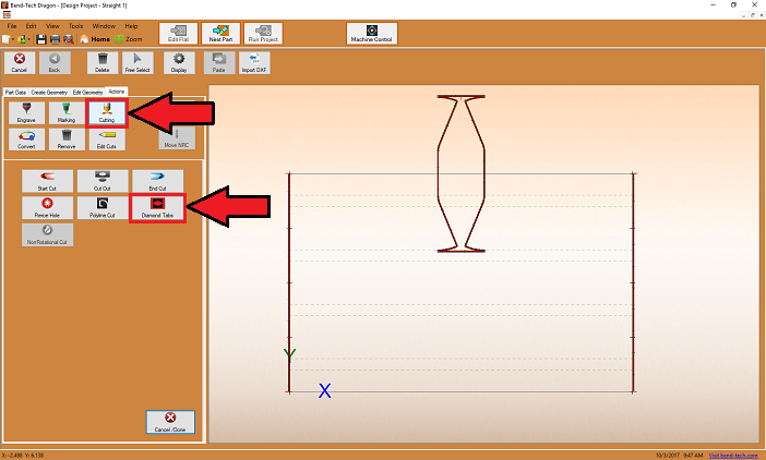
22. Then, select the Cutting button followed by the Diamond Tabs button.
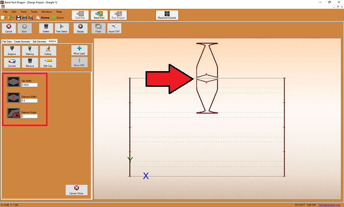
23. Lastly, leave the notch dimensions as they are and select the center of your notch to place the bridging option as shown below.
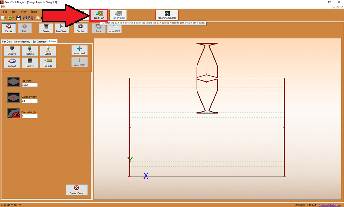
24. Now that the part is finished, you are free to adjust/edit any other geometry in this interface, or to send this part to the nesting interface using the Nest Part button located at the top of the screen.
25. Here, you can designate the stock length of your tubing in the Setup tab, add your part to the stock length in the Parts tab, and view the machine order of actions in the Shifts tab.
26. Finally, you can send the job to the machine by selecting the Run Project button at the top of the screen.
