Difference between revisions of "Dragon Calibration"
| Line 323: | Line 323: | ||
*Watch the video [https://www.youtube.com/watch?v=mXe0Jc0KqOA HERE] | *Watch the video [https://www.youtube.com/watch?v=mXe0Jc0KqOA HERE] | ||
| + | |||
| + | |||
| + | |||
| + | |||
| + | |||
Revision as of 15:01, 18 May 2016
"This guide will help you understand all of the processes and procedures involved in assembling your Dragon Machine and calibrating your Dragon Software to your machine."
"Please take your time in assembling and calibrating your new Dragon Machine/Software by following all of these steps thoroughly. This should take anywhere from 2-3 hours based on how you pay attention to detail, how much help you have and if you are technologically adept or not."
"Each step will have a short video attached to it showing how that particular step is meant to be completed by the operator."
Contents
- 1 Introduction
- 2 Select Computer Setup
- 3 Chuck Travel (X Axis)
- 4 Chuck Rotation (Y Axis)
- 5 Toolset Height Control (Z Axis)
- 6 A-Axis Movement: Tool Change
- 7 Check Homing Switch (X Axis)
- 8 Check Homing Switch (A Axis)
- 9 Rapid Travel
- 10 Laser Centering
- 11 Marker Centering
- 12 Marker Alignment (X-Axis)
- 13 Marker Height Adjustment
- 14 Marker Calibration: Verify
- 15 Engraver Centering
- 16 Engraver Alignment (X-Axis)
- 17 Engraver Height Adjustment
- 18 Engraver Calibration: Verify
- 19 Torch Centering
- 20 Torch Alignment (X-Axis)
- 21 Torch Height Adjustment
- 22 Torch Calibration: Verify
Introduction
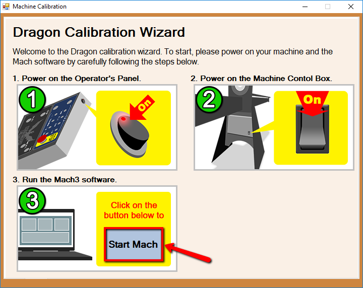
- This introduction gives you a small insight into the tasks that are expected during this calibration and instructs you to turn on the power on the control panel and on the Dragon machine.
- When the machine is turned on, click the "Start Mach" button to continue to the next page.
Select Computer Setup
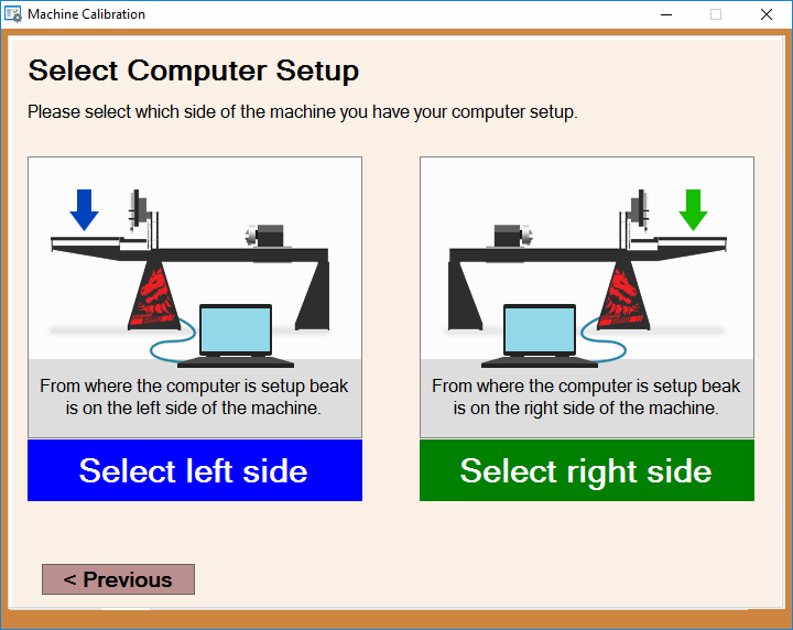
- The "Select Computer Setup" page will open your Mach program and it will ask you which side of the Dragon machine your computer is located on.
- Select the image that describes your computer's location in reference to the Dragon machine to move on to the next page in the calibration.
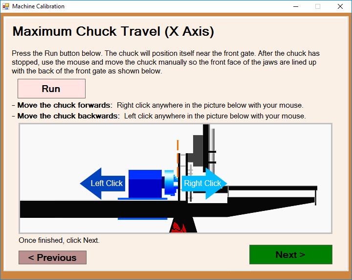
Chuck Travel (X Axis)
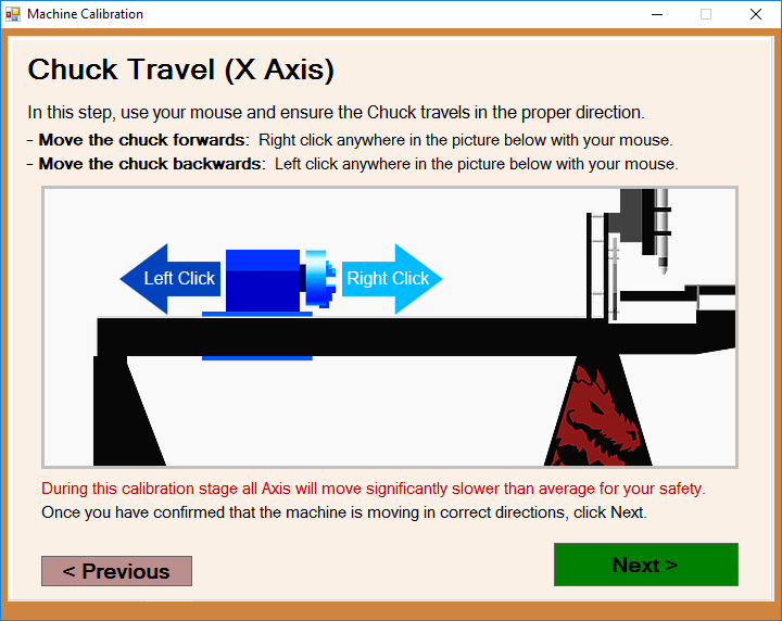
- This page will prompt you to adjust the chuck travel to ensure that it is moving in the proper direction when you press the left and right buttons on your mouse.
- Watch the video HERE
Chuck Rotation (Y Axis)
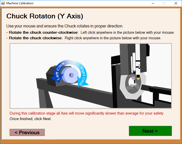
- This page will prompt you to adjust the chuck rotation to ensure that it is rotating in the proper direction when you press the left and right buttons on your mouse.
- Watch the video HERE
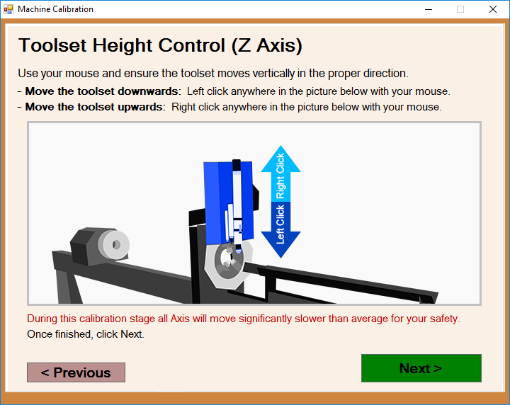
Toolset Height Control (Z Axis)
- This page will prompt you to adjust the tool height to ensure that the toolset is moving in the proper direction when you press the left and right buttons on your mouse.
- Watch the video HERE
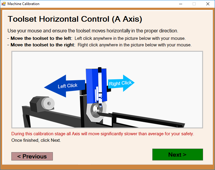
A-Axis Movement: Tool Change
- This page will prompt you to adjust the toolset's horizontal movement to ensure that it is moving in the proper direction when you press the left and right buttons on your mouse.
- Watch the video HERE
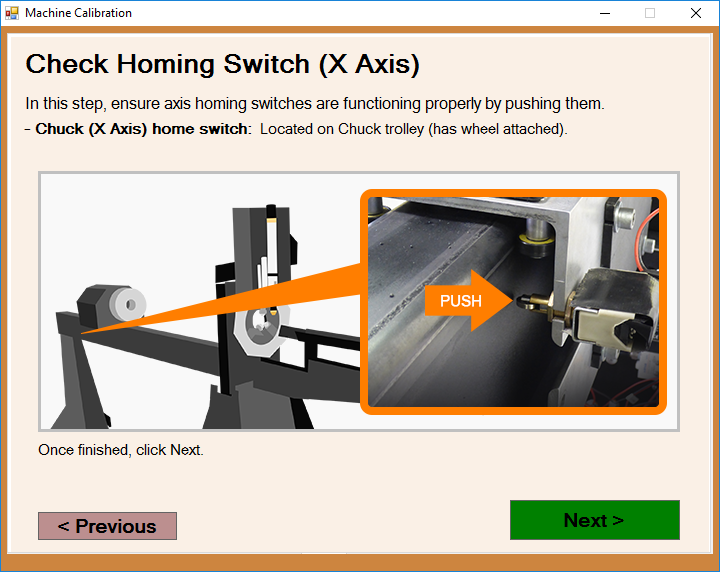
Check Homing Switch (X Axis)
- The page will point to the manual switch for the X axis. You are prompted to press the X axis switch followed the Next button.
- Watch the video HERE
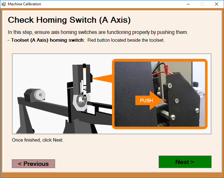
Check Homing Switch (A Axis)
- The page will point to the manual switch for the A axis. You are prompted to press the A axis switch followed the Next button.
- Watch the video HERE
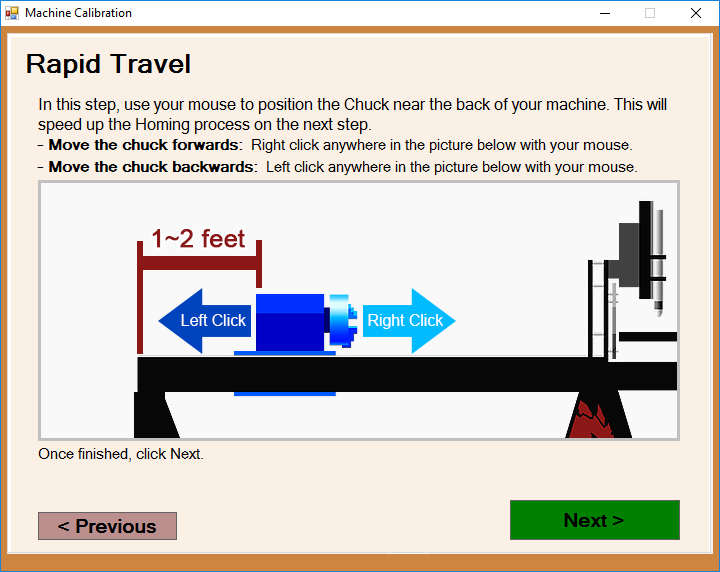
Rapid Travel
- This page will prompt you to move the chuck near the back of the machine using the left and right buttons on your mouse.
- Watch the video HERE
Laser Centering
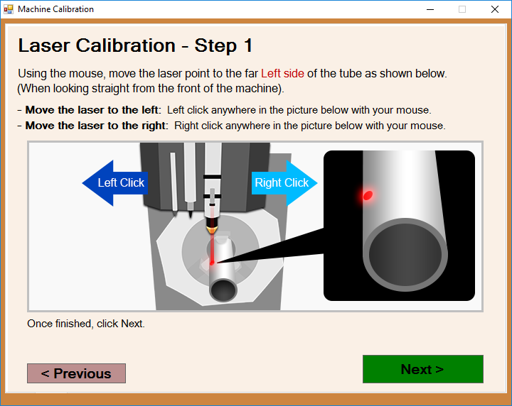
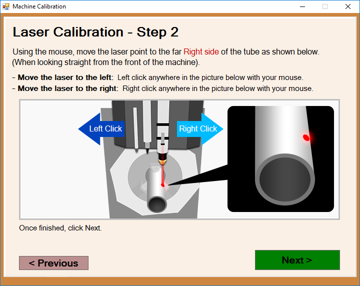
- This page will prompt you to use the Feed + and Feed - buttons to move the laser left and right to find one side of the tubing. It doesn't matter what side of the tubing you choose.
- Next, press the Feed 100% button to register the information with the software. Then, you will be prompted to find the other side and press the Feed 100% button.
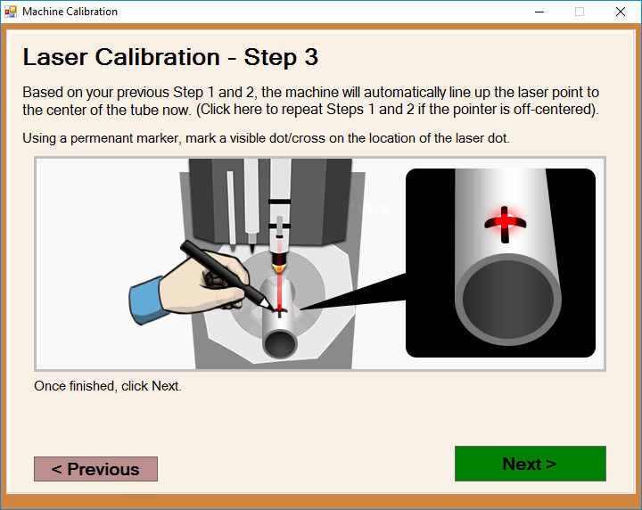
- Finally, place a dot with a marker at the exact point where the laser hits the tubing.
- Watch the video HERE
Marker Centering
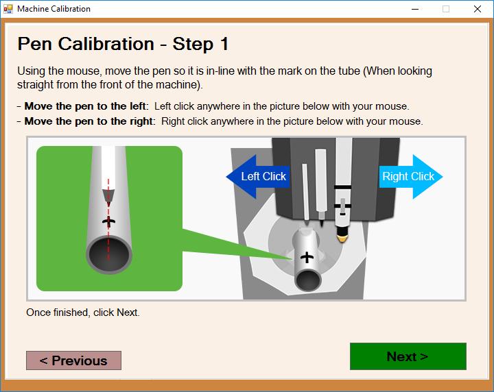
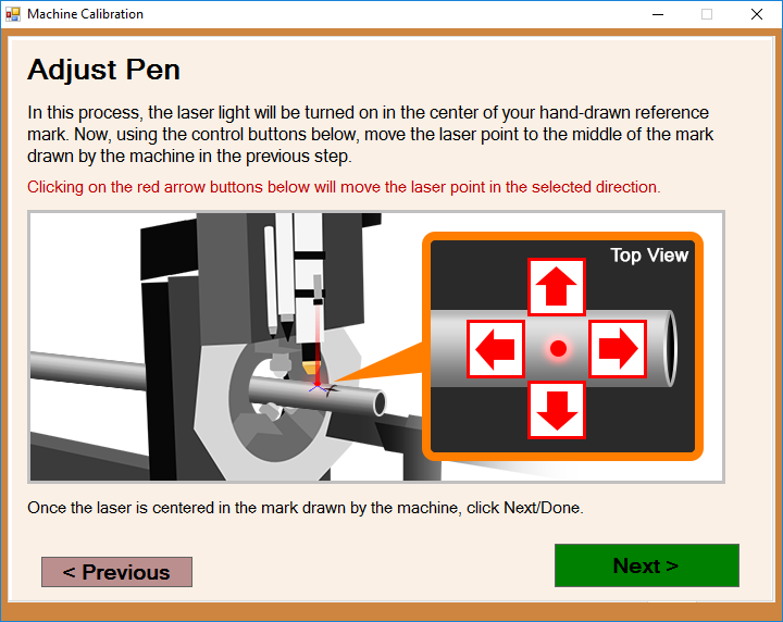
- This page will prompt you to use the Feed + and Feed - buttons to move the marker left and right (A-Axis) to find the center of the tubing. Next, press the Feed 100% button to register the information with the software.
- Watch the video HERE
Marker Alignment (X-Axis)
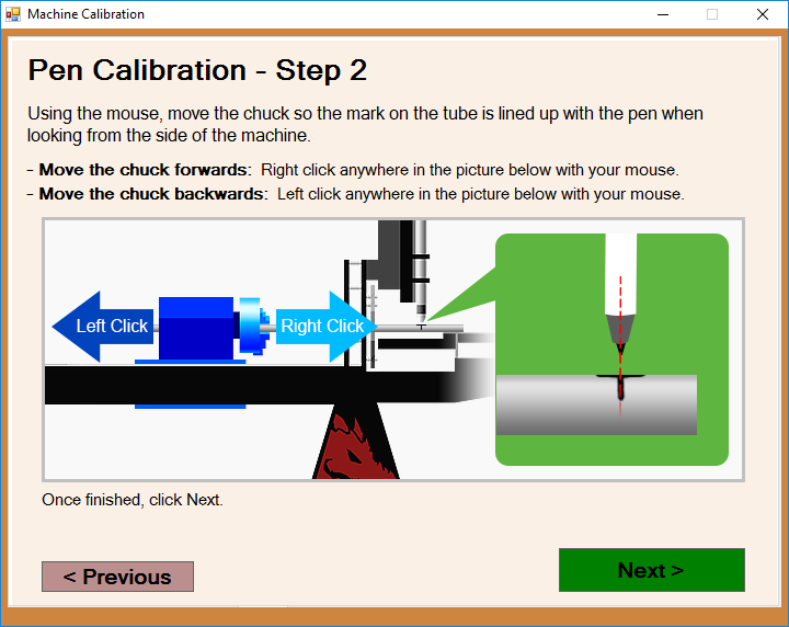
- This page will prompt you to use the Feed + and Feed - buttons to move the marker along the length of the tubing (X-Axis) until it touches the mark you've created on the center of the tubing. Next, press the Feed 100% button to register the information with the software.
- Watch the video HERE
Marker Height Adjustment
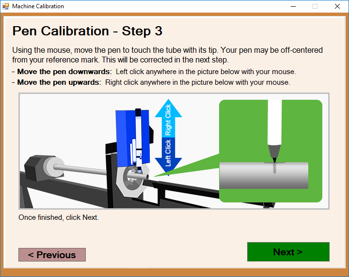
- This page will prompt you to use the Feed + and Feed - buttons to move the marker up and down (Z-Axis) until it touches the center of the tubing. Next, press the Feed 100% button to register the information with the software.
- Watch the video HERE
Marker Calibration: Verify
- This page will prompt you to make any adjustments to either the A, X or Z-Axes. Keep in mind that values entered are read in inches or millimeters based on your Options settings.
- The green lettering indicates that a positive number will move the adjustment left (A-Axis), forward (X-Axis) or down (Z-Axis), and a negative number will move the adjustment right (A-Axis), back X-Axis) or up (Z-Axis).
- If you'd like to change any of the previous steps, you can always press the Back' button and adjust them from there as well.
- Watch the video HERE
Engraver Centering
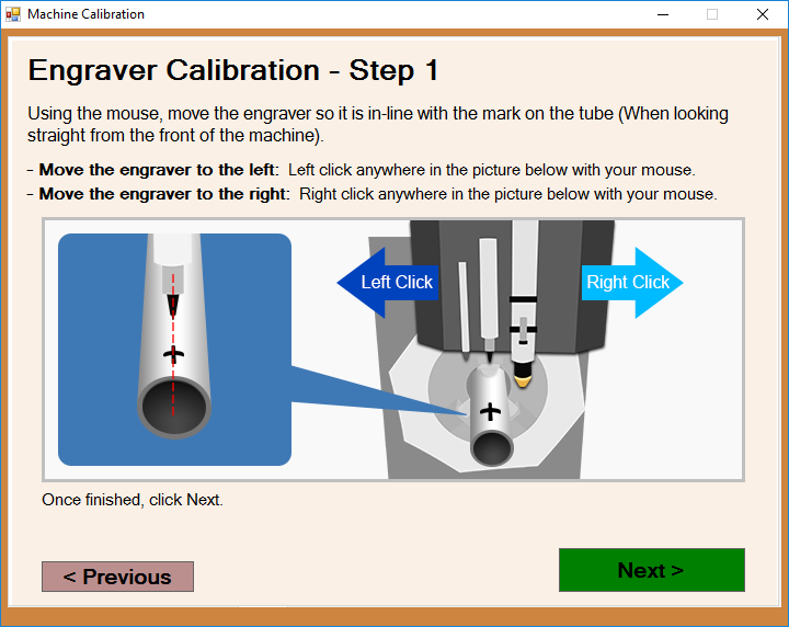
- This page will prompt you to use the Feed + and Feed - buttons to move the engraver left and right (A-Axis) to find the center of the tubing. Next, press the Feed 100% button to register the information with the software.
- Watch the video HERE
Engraver Alignment (X-Axis)
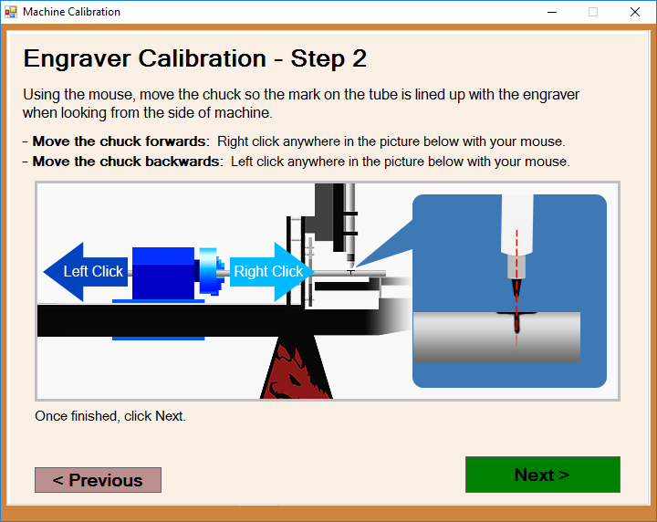
- This page will prompt you to use the Feed + and Feed - buttons to move the engraver along the length of the tubing (X-Axis) until it touches the mark you've created on the center of the tubing. Next, press the Feed 100% button to register the information with the software.
- Watch the video HERE
Engraver Height Adjustment
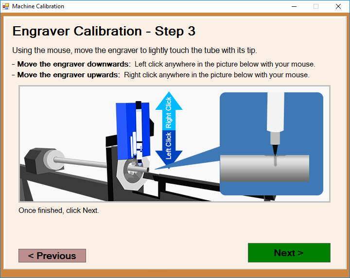
- This page will prompt you to use the Feed + and Feed - buttons to move the engraver up and down (Z-Axis) until it touches the center of the tubing. Next, press the Feed 100% button to register the information with the software.
- Watch the video HERE
Engraver Calibration: Verify
- This page will prompt you to make any adjustments to either the A, X or Z-Axes. Keep in mind that values entered are read in inches or millimeters based on your Options settings.
- The green lettering indicates that a positive number will move the adjustment left (A-Axis), forward (X-Axis) or down (Z-Axis), and a negative number will move the adjustment right (A-Axis), back X-Axis) or up (Z-Axis).
- If you'd like to change any of the previous steps, you can always press the Back' button and adjust them from there as well.
- Watch the video HERE
Torch Centering
- This page will prompt you to use the Feed + and Feed - buttons to move the torch left and right (A-Axis) to find the center of the tubing.
- You will have to click the Back button until you reach the Engraver Height Adjustment page to raise the toolset for this step. Then, press next to return to the Torch Centering page and use the Feed + and Feed - buttons to move the torch to the center.
- Next, press the Feed 100% button to register the information with the software.
- Watch the video HERE
Torch Alignment (X-Axis)
- This page will prompt you to use the Feed + and Feed - buttons to move the torch along the length of the tubing (X-Axis) until it touches the mark you've created on the center of the tubing. Next, press the Feed 100% button to register the information with the software.
- Watch the video HERE
Torch Height Adjustment
- This page will prompt you to use the Feed + and Feed - buttons to move the torch up and down (Z-Axis) until it touches the center of the tubing. Next, press the Feed 100% button to register the information with the software.
- Watch the video HERE
Torch Calibration: Verify
- This page will prompt you to make any adjustments to either the A, X or Z-Axes. Keep in mind that values entered are read in inches or millimeters based on your Options settings.
- The green lettering indicates that a positive number will move the adjustment left (A-Axis), forward (X-Axis) or down (Z-Axis), and a negative number will move the adjustment right (A-Axis), back X-Axis) or up (Z-Axis).
- If you'd like to change any of the previous steps, you can always press the Back' button and adjust them from there as well.
- Watch the video HERE
