Difference between revisions of "Dimension Location"
| Line 20: | Line 20: | ||
With this bender you need to set the “Dimension Location” under the “Settings” tab to “Start”. This will place the bend location values to the start of the bend. | With this bender you need to set the “Dimension Location” under the “Settings” tab to “Start”. This will place the bend location values to the start of the bend. | ||
| − | DisplayLocation1. | + | [[File:DisplayLocation1.jpg]] [[File:DisplayLocation2.jpg]] |
| Line 32: | Line 32: | ||
With this bender you need to set the “Dimension Location” under the “Settings” tab to “End”. This will place the bend location values to the end of the bend. | With this bender you need to set the “Dimension Location” under the “Settings” tab to “End”. This will place the bend location values to the end of the bend. | ||
| − | DisplayLocation3. | + | [[File:DisplayLocation3.jpg]] [[File:DisplayLocation4.jpg]] |
| Line 43: | Line 43: | ||
With this bender you need to set the “Dimension Location” under the “Settings” tab to “Center”. This will place the bend location values to the center of the bend. | With this bender you need to set the “Dimension Location” under the “Settings” tab to “Center”. This will place the bend location values to the center of the bend. | ||
| − | DisplayLocation5. | + | [[File:DisplayLocation5.jpg]] [[File:DisplayLocation6.jpg]] |
'''NOTE: The “Dim Location” global default is found under the “Tools” , “Options” pull down and then search for the “Design Settings” tab. Always press “Apply”, “OK” to update your changes.''' | '''NOTE: The “Dim Location” global default is found under the “Tools” , “Options” pull down and then search for the “Design Settings” tab. Always press “Apply”, “OK” to update your changes.''' | ||
| − | DisplayLocation7. | + | [[File:DisplayLocation7.jpg]] |
Revision as of 14:23, 9 June 2014
Determining your style of bender
Your style of bender is critical as to how the software needs to be set up.
We will break this down into 3 styles of benders:
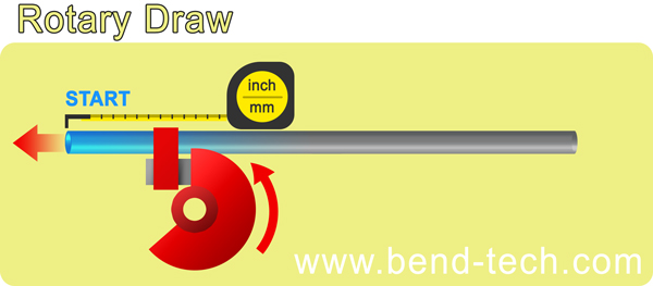
1) Rotary Draw
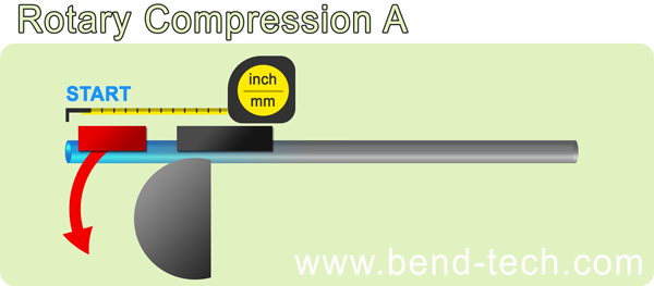
2) Rotary Compression
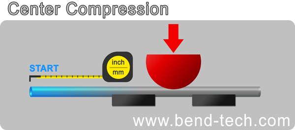
3) Center Compression
Rotary Draw Bender:
This style of bender allows for the main center die to rotate as the material is being drawn into it.
Some examples of this bender are: Pro-Tools 105 and 1 Shot, JD2 Model 2 & 3, Ercolina, Ineco and any mandrel bender
With this bender you need to set the “Dimension Location” under the “Settings” tab to “Start”. This will place the bend location values to the start of the bend.
Rotary Compression Bender:
This style of bender leaves the center die stationary and uses a follower or pusher die to wrap the tubing around the die.
Some examples of this bender are: JD2 Model 4. Hossfeld
With this bender you need to set the “Dimension Location” under the “Settings” tab to “End”. This will place the bend location values to the end of the bend.
Center Compression Bender:
This style of bender pushes the material in the middle of the bend and wraps the material down both sides of a die.
Some examples of the bender are: HF bottle jack bender, Sheet metal press brake
With this bender you need to set the “Dimension Location” under the “Settings” tab to “Center”. This will place the bend location values to the center of the bend.
NOTE: The “Dim Location” global default is found under the “Tools” , “Options” pull down and then search for the “Design Settings” tab. Always press “Apply”, “OK” to update your changes.


