Difference between revisions of "Copy and Paste Flanges"
| Line 9: | Line 9: | ||
This will be the part we create: | This will be the part we create: | ||
| − | FinishedFlange. | + | [[File:FinishedFlange.jpg]] [[File:FinishedFlange2.jpg]] |
Start by creating the 1st flange: | Start by creating the 1st flange: | ||
| − | Flange1. | + | [[File:Flange1.jpg]] |
Revision as of 15:02, 9 June 2014
This example is slightly more complicated than most because of the part example we selected. The difference being the angle of how the bend comes off.
Before we get started a couple of items should be noted:
Note 1) The angle of a part in the Geometric Library is based upon the bend it was designed from. The geometry will be rotated to follow the bend line if it were laying horizontal.
Note 2) If the outside of a flange is updated to the Geometric Library, do not bring along the bend line. This will cause 2 lines on top of each other and difficult to remove the correct one.
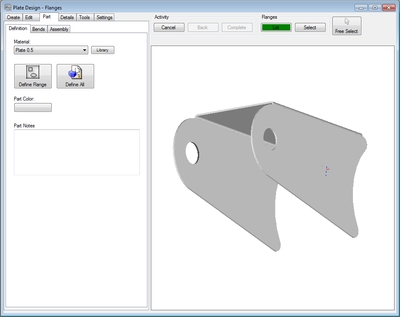
This will be the part we create:
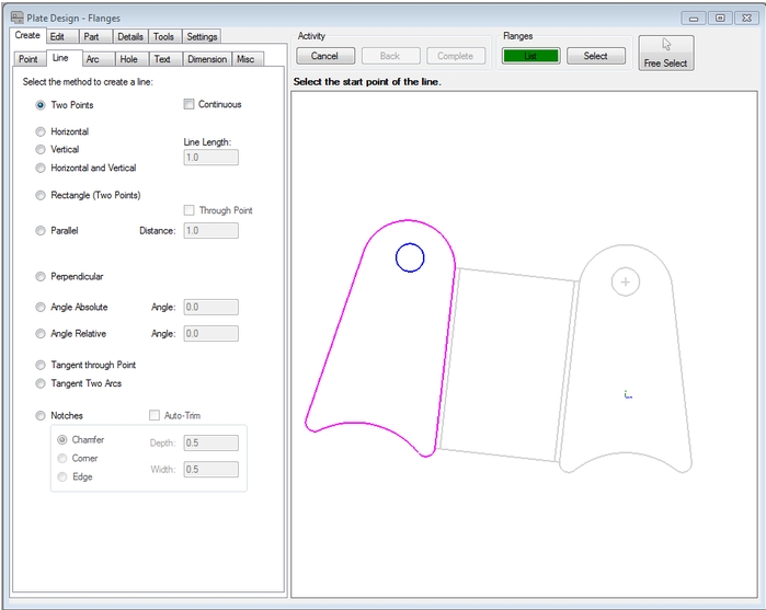
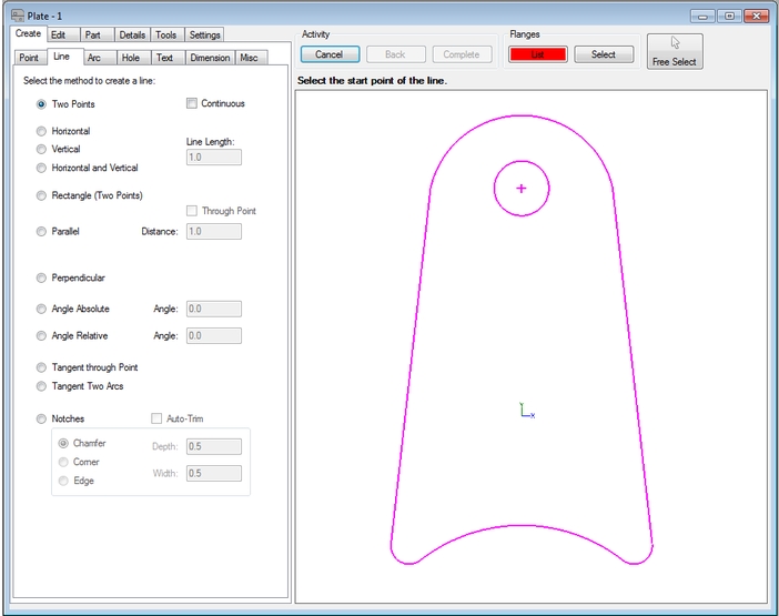
Start by creating the 1st flange:
To add the flange to the Geometric Library, select the "Tools" tab and click "Create Item". The software will ask you to select the feature(s) you want to add to the library. Notice we have selected all but the one we will add the bend line to. Use the "Complete" button at the top of the window. Now select the anchor location. Shown in our picture with the red circle. The software will now ask for a name. In our example, we gave it a name of "shock mount side".
Flange2.png
Add the bend(s) as needed.
Flange3.png
Flange4.png
On the last flange we removed the lines of the flange except the bend line.
Flange5.png
We are going to add or flange from the Geometric Library. One thing we are going to need to know is the angle the flange needs to be in relation to our new flange. To do this we need to find one of are angles. Select the "List" button in the "Flange" frame above the graphics window. This will bring down a list of flanges. Select "Base Flange". Go to the Details tab and find the line that is circled below in the list. In our example we have an angle of 276.34 (we will use the 6.34) part of the number. This is the part that makes our example a little more difficult than what most uses will be of the library.
Flange6.png
WARNING: Make sure you go back to our last flange. Select the "List" button in the "Flange" frame above the graphics window. This will bring down a list of flanges. Select last flange in the list. You will find our last flange now highlighted (should be just the bend line).
Now we will add the flange. Select the "Tools" tab and the "Paste Item" button. This will bring up the Geometric Library. Select the item you would like to use. In our example we need to "Mirror Vertically" and add an angle of -12.68 (This angle is double of what we verified in our case and also swings the other direction so we added the - [negative] sign). Now select the "OK" button.
Flange7.png
Select the point that matches up to your anchor point:
Flange8.png
Select the "Part"-----> "Definition" -----> "Define Flange" button. Select the new flange.
Flange9.png
If any gaps are left in the outline, they will need to be filled in by adding lines or other features. In this case, it worked out properly, so no further steps need to be taken.


