Difference between revisions of "Cutting"
| Line 22: | Line 22: | ||
Click the "'''Auto-Miter'''" [[File:auotmiter1.png]] button to extend the lengths of intersecting tubes past their center line so they can be cut equally. | Click the "'''Auto-Miter'''" [[File:auotmiter1.png]] button to extend the lengths of intersecting tubes past their center line so they can be cut equally. | ||
| − | [[File:auto-miter1.png]][[File:auto-miter2.png]] | + | [[File:auto-miter1.png]][[File:auto-miter2.png]][[File:auto-miter3.png]] |
| + | |||
| + | [[File:auto-miter4.png]][[File:auto-miter4.png]] | ||
<h3>Cutting Plane</h3> | <h3>Cutting Plane</h3> | ||
Revision as of 12:42, 13 November 2014
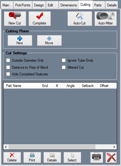
The Cutting tab contains the tools necessary for adding cuts to the ends of parts. Wrappers can be printed which, when wrapped around the end of a tube, mark where the tube needs to be cut.
Make Cuts
Click the "New Cut" ![]() button and click a part. The cut part will be highlighted in green once selected. Click a second part, plane, or multiple parts that the first part will be cut to fit against. The second and any consecutive selected parts will be highlighted in red. Click the "Complete"
button and click a part. The cut part will be highlighted in green once selected. Click a second part, plane, or multiple parts that the first part will be cut to fit against. The second and any consecutive selected parts will be highlighted in red. Click the "Complete" ![]() button. The cut should appear in the list of cuts on the Cutting tab and shown on the assembly.
button. The cut should appear in the list of cuts on the Cutting tab and shown on the assembly.
Click the "Auto-Cut" ![]() button to let the software attempt to generate all cuts in the assembly project.
button to let the software attempt to generate all cuts in the assembly project.
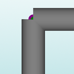
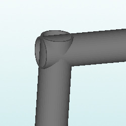
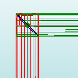
Click the "Auto-Miter" ![]() button to extend the lengths of intersecting tubes past their center line so they can be cut equally.
button to extend the lengths of intersecting tubes past their center line so they can be cut equally.
Cutting Plane
Using the cutting plane feature, a custom plate can be defined and used to place cuts anywhere on the assembly design.
To place a cutting plane, click the New button ![]() and click on a PickPoint to define the center/base point of the plane. Then click the first direction and second direction of the plane. Once a plane is place in the assembly, it can be used as a cutting feature and will allow straight cuts to be placed anywhere.
and click on a PickPoint to define the center/base point of the plane. Then click the first direction and second direction of the plane. Once a plane is place in the assembly, it can be used as a cutting feature and will allow straight cuts to be placed anywhere.
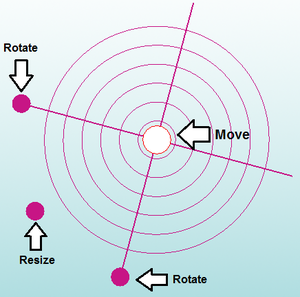
To move the plane, click the Move button. Then click and drag the move tools directly on the plane to move, resize, and rotate the plane. See image below.
Cut Settings
If the Outside Diameter Only option is checked, the software will not display the inside diameter cut line for each cut.
If Distance to Perp of Bend is checked, the cut wrapper's red line will instead display the distance to the tangent of the nearest bend combined with the outside radius of the bend.
If the Hide Completed Features option is checked,
If the Ignore Tube Ends option is checked,
If Mitered Cut is checked, all cuts will be calculated as straight mitered cuts. If you are using a hole saw to cut your tubes leave Mitered Cut unchecked.
Cut Chart
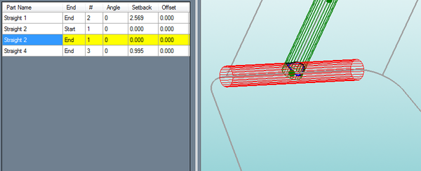
A chart displaying a list of all the cuts currently applied to the assembly will be shown as well.
Click on a cut to see a preview of the cut on the 3D model of the assembly.
Click Delete ![]() to remove the cut from the tube, or click Delete All
to remove the cut from the tube, or click Delete All ![]() to remove all cuts from the Assembly project.
to remove all cuts from the Assembly project.
Click Print ![]() to print the currently selected wrapper, or click Print All
to print the currently selected wrapper, or click Print All ![]() to print out all wrappers for the entire Assembly project.
to print out all wrappers for the entire Assembly project.
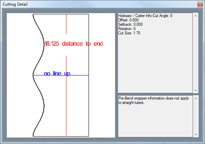
Click the Details button ![]() to see a preview of the cutting wrapper. On each wrapper, there is a red line with a number on it. This line is used for lining up a wrapper on a tube. The number is the distance from the end of the tube that the red line should be.
to see a preview of the cutting wrapper. On each wrapper, there is a red line with a number on it. This line is used for lining up a wrapper on a tube. The number is the distance from the end of the tube that the red line should be.
Click the Select button ![]() and click on a cut in the display area to select it from the assembly directly.
and click on a cut in the display area to select it from the assembly directly.
