Difference between revisions of "Dragon Calibration"
| Line 289: | Line 289: | ||
*The page will point to the manual switches for the X and A axes. You are prompted to press the X axis switch and the Next button, then the A axis switch and the next button. | *The page will point to the manual switches for the X and A axes. You are prompted to press the X axis switch and the Next button, then the A axis switch and the next button. | ||
| − | |||
| − | |||
| Line 327: | Line 325: | ||
*This page will prompt you to load a piece of test material and enter the outer diameter (OD) and material length in the text fields provided. | *This page will prompt you to load a piece of test material and enter the outer diameter (OD) and material length in the text fields provided. | ||
| + | |||
Revision as of 07:22, 28 October 2015
"This guide will help you understand all of the processes and procedures involved in assembling your Dragon Machine and calibrating your Dragon Software to your machine."
"Please take your time in assembling and calibrating your new Dragon Machine/Software by following all of these steps thoroughly. This should take anywhere from 2-3 hours based on how you pay attention to detail, how much help you have and if you are technologically adept or not."
"Each step will have a short video attached to it showing how that particular step is meant to be completed by the operator."
Contents
Introduction
- This introduction gives you a small insight into the tasks that are expected during this calibration and reminds you that you will click the "Next" button after each step has been completed.
- You may also click the "Back" button if you have skipped a step accidentally or if you have to revise a step in any way.
Basic Assembly
- The "Basic Assembly" page will allow you to watch a video of the machine being assembled and will also contain a link that will allow you to print out step by step instructions on how to assemble it.
- A copy of the instructions for assembly can be found here.
Electrical Connections
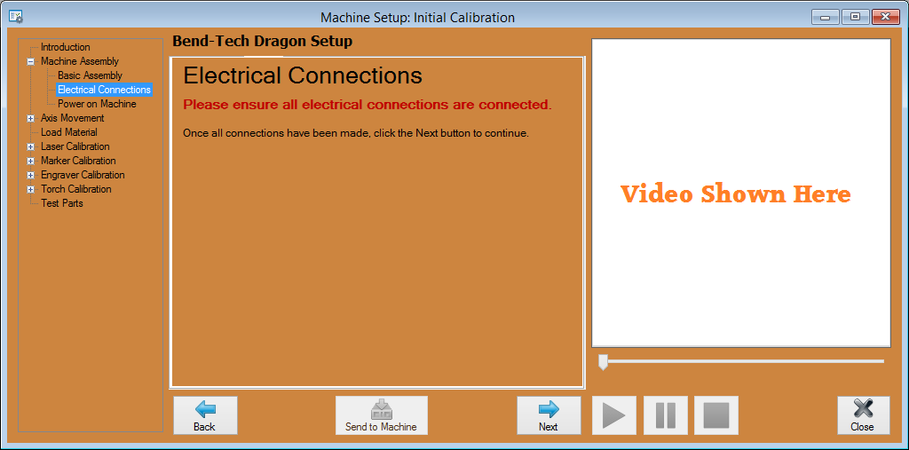
- This page will explain and show video of how "Electrical Connections" are set up and the locations of each connection that needs to be made before calibration and operation of the machine.
Power on the Machine
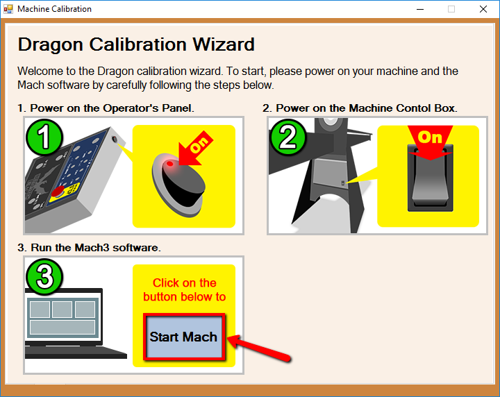
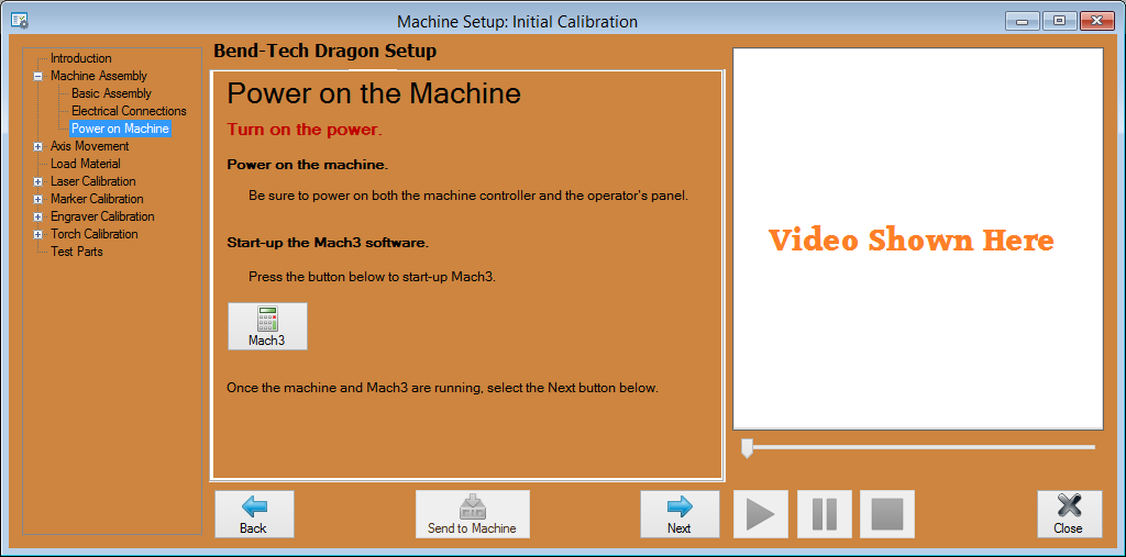
- This page will indicate the Two power switches that must be turned on in order to run the machine and it will prompt you to open the "Mach 3" software program.
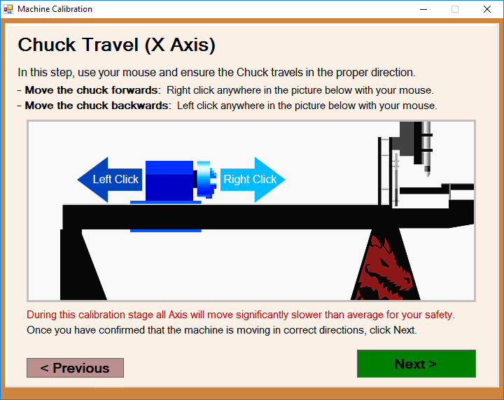
X-Axis Movement: Chuck Travel
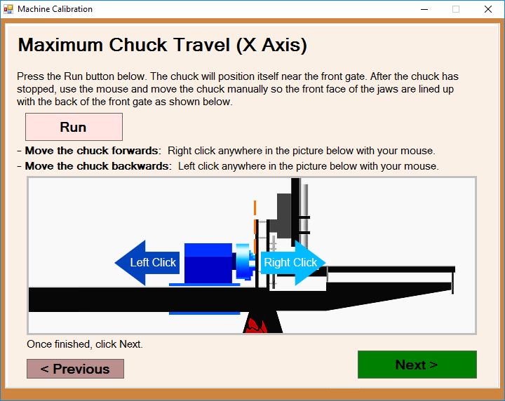
- This page will prompt you to adjust the chuck travel to ensure that it is moving in the proper direction when you press the Feed + and Feed - buttons on the control panel.
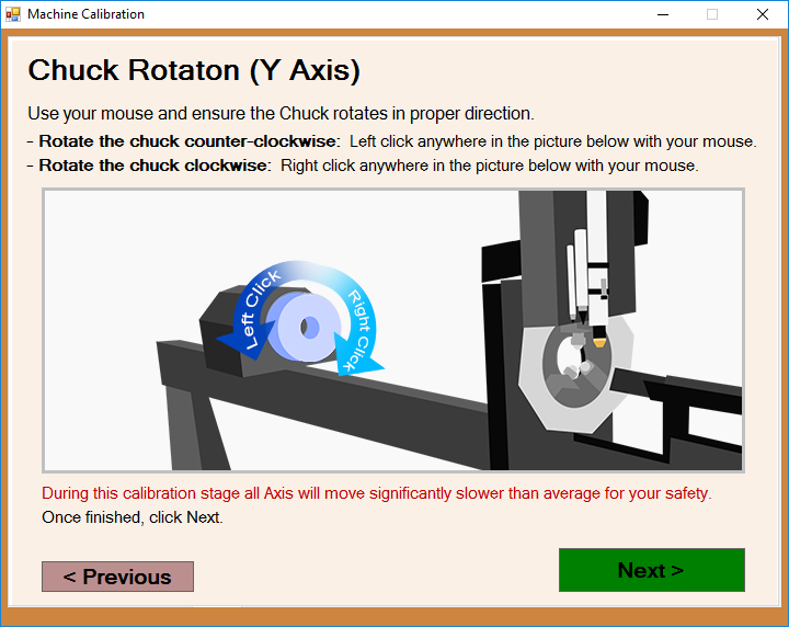
Y-Axis Movement: Chuck Rotation
- This page will prompt you to adjust the chuck rotation to ensure that it is rotating in the proper direction when you press the Feed + and Feed - buttons on the control panel.
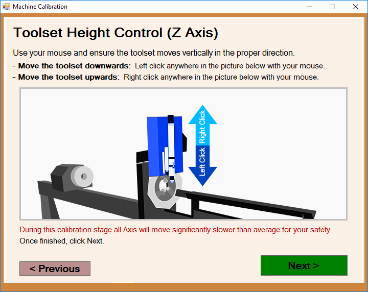
Z-Axis Movement:Tool Height
- This page will prompt you to adjust the tool height to ensure that the toolset is moving in the proper direction when you press the Feed + and Feed - buttons on the control panel.
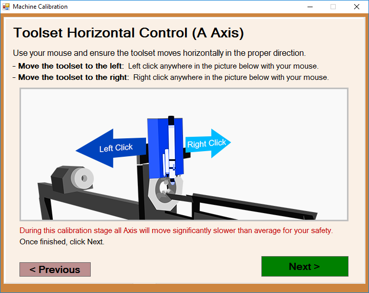
A-Axis Movement: Tool Change
- This page will prompt you to adjust the toolset's horizontal movement to ensure that it is moving in the proper direction when you press the Feed + and Feed - buttons on the control panel.
Axis Homing
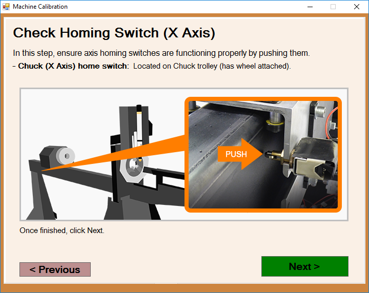
- The page will point to the manual switches for the X and A axes. You are prompted to press the X axis switch and the Next button, then the A axis switch and the next button.
Load the Material
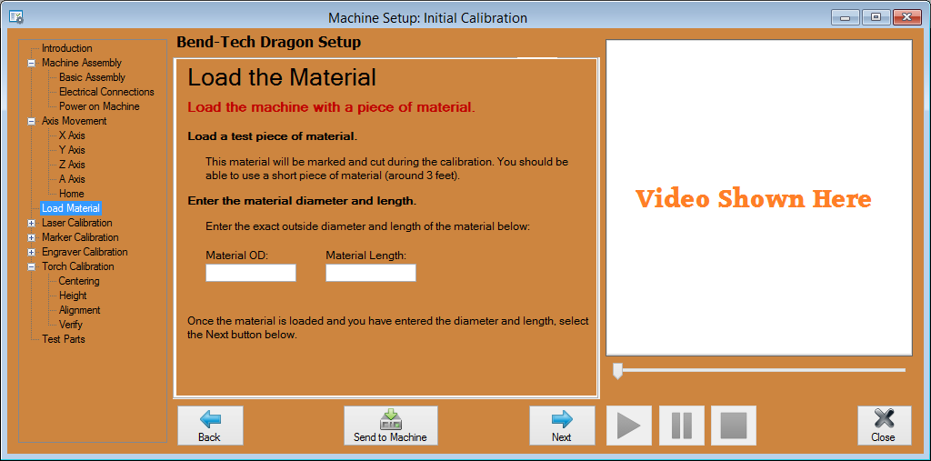
- This page will prompt you to load a piece of test material and enter the outer diameter (OD) and material length in the text fields provided.
Laser Centering
- This page will prompt you to use the Feed + and Feed -' buttons to move the laser left and right to find one side of the tubing. It doesn't matter what side of the tubing you choose. Next, press the Feed 100% button to register the information with the software. Then, you will be prompted to find the other side and press the Feed 100% button.
