Difference between revisions of "Dragon Custom Design Tutorial"
| Line 102: | Line 102: | ||
20. Then, in the '''Extinguish Settings''' section, change the '''Extinguish Type:''' to '''Arc''', the '''Angle/Sweep:''' to '''25''' and enter '''0.25''' into the '''Radius:''' value field as well. Then, click the '''OK''' button. | 20. Then, in the '''Extinguish Settings''' section, change the '''Extinguish Type:''' to '''Arc''', the '''Angle/Sweep:''' to '''25''' and enter '''0.25''' into the '''Radius:''' value field as well. Then, click the '''OK''' button. | ||
| − | [[File: | + | [[File:Dragon_Edit_Cuts6.png]] |
[[File:Dragon_Action_Edit_Cuts7.png]] | [[File:Dragon_Action_Edit_Cuts7.png]] | ||
Revision as of 11:39, 24 May 2016
Things To Know
- This tutorial will step you through the process of creating geometry on a straight design in Bend-Tech Dragon and show you the possible choices for where to take it next depending on your needs. As you walk through this tutorial, procedures are designed based on your knowledge of earlier procedures. Because of this, it is very important that you carefully step through this guide, understanding everything along the way.
If you have not completed the Dragon Straight Part Tutorial, please do so before continuing any further.
Tutorial
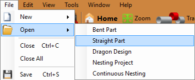
1. Start by opening the Bend-Tech Dragon software and opening the file saved from the Dragon Straight Part Tutorial labeled Dragon Test1. Do this by selecting File - Open - Straight Part from the top left of the window, selecting the file, then clicking the Open button.
2. With the straight part design open, maximize the screen ![]() and click on the Transfer to Design
and click on the Transfer to Design ![]() button at the top of the screen.
button at the top of the screen.
3. Now, in the custom design interface, select the Create Geometry ![]() tab and select the Incremental
tab and select the Incremental ![]() option below to start plotting out some points in the design. You should be under the Point sub-tab during this step.
option below to start plotting out some points in the design. You should be under the Point sub-tab during this step.
4. Under the Incremental option currently selected, type 6 in the X value field and 2.75 in the Y value field.
5. Next, select the lower most left hand corner of the unfolded tube to place a point 6 inches right and 2.75 inches upwards from the origin.
6. Now, Replace the 2.75 in the Y value field with a 0.
7. Next, click on our previously laid point to place a point 6 inches to the right of it.
8. Now, click on the new point and place another point 6 inches to the right.
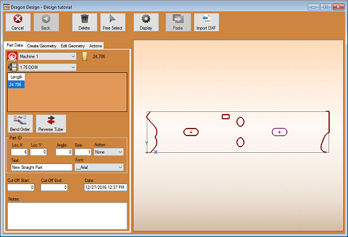
9. Next, switch to the Hole ![]() sub-tab and place 3 one inch diameter holes on each of our points. Simply click on the points individually. The default hole diameter is already set to 1 inch.
sub-tab and place 3 one inch diameter holes on each of our points. Simply click on the points individually. The default hole diameter is already set to 1 inch.
10. Now, with three holes along the center of our unfolded part, click over to the Actions ![]() tab and prepare to assign machine actions to this new geometry.
tab and prepare to assign machine actions to this new geometry.
11. In the Actions tab, first select the Marking  button to the left and then click on the first hole we've created in the design. This will cause the hole to turn green (if no changes have been made to the default color) and will cause the Dragon machine to mark this hole with a marker.
12. Next, select the Engrave  button to the left and then click on the second hole we've created in the design. This will cause the hole to turn purple (if no changes have been made to the default color) and will cause the Dragon machine to engrave this hole with an engraver.
13. Finally, select the Cutting  button and the Cutout
 ![]() option followed by the third hole we've created in the design. This will cause the hole to turn dark red (if no changes have been made to the default color) and will cause the Dragon machine to cut this hole out with the plasma torch.
option followed by the third hole we've created in the design. This will cause the hole to turn dark red (if no changes have been made to the default color) and will cause the Dragon machine to cut this hole out with the plasma torch.
See the Dragon Guide for further explanation of these functions and much, much more!
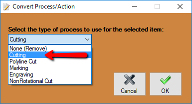
14. Now, still under the Actions tab, select the Convert button to the far left followed by the first hole in the design. A window will appear prompting you to select a new action for the selected geometry. Select the Cutting option from the drop down menu and click the OK button.
15. Lastly, with the Convert button still selected click on the second hole in the design. A window will appear prompting you to select a new action for the selected geometry. Select the Cutting option from the drop down menu and click the OK button.
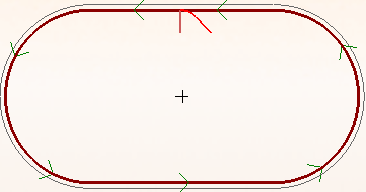
16. The Lead In and Lead Out locations for the plasma torch cuts are indicated by small red lines located on the outer edges of the start and end cuts and on the inner edges of the hole cutouts. These make up the section for the pierce location and the short distance needed to ease into the cut profile.
17. Now, select the Move Lead  button to the left of the display screen and select the lead from the starting cut profile on the lower left corner of the tube. Then, click in the center-most section of the cut profile to place the lead there. You will have to zoom in close with the wheel on your mouse for this step.
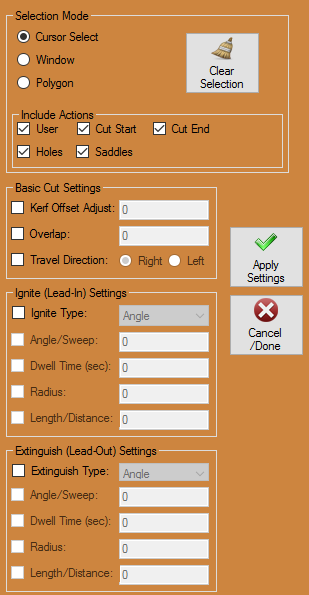
18. Finally, the Edit Cuts button will allow you to edit how the cuts will occur in the cutting process. Select the Edit Cuts  button followed by any of the red cutouts we've been working with and a window will appear where you can edit the settings for the cut.
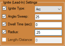
19. Here, you will be able to alter settings for both the Ignite and Extinguish settings. Start in the Ignite Settings section by changing the Ignite Type: to Arc, enter 25 into the Angle/Sweep: value field and enter 0.25 into the Radius: value field.
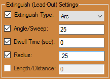
20. Then, in the Extinguish Settings section, change the Extinguish Type: to Arc, the Angle/Sweep: to 25 and enter 0.25 into the Radius: value field as well. Then, click the OK button.
21. With the part now completed, we will save it off for future use with the Dragon Nesting Tutorial. So, select the Save ![]() icon from the icon menu bar at the top of the screen and name it Dragon Test2.
icon from the icon menu bar at the top of the screen and name it Dragon Test2.
Thank you for participating in this tutorial.
Transferring
- After applying all of the changes to our straight part, we are free to select the desired option for transferring the part out.
- You may now Transfer to Nesting
 if you'd like the current part to be added to a nesting project without altering the part further.
- See the Dragon guide to help you decide where to go from here.
