Handrail Tutorial
(UNDER CONSTRUCTION) See Handrail Module for temporary assistance regarding the Handrail Module.
Thank you for your patience.
Contents
Railing Design
- This tutorial will begin by showing how to create a length of railing with desired values designed with PickPoints.
- For this reason, the default walls, platforms and steps will all be used. (please note that these features can be easily altered to fit the user's needs after they are placed in the display area.
- If you're not familiar with this interface, it is suggested that you visit the Handrail Module page for better understanding of the basics.
- Read and follow ALL instructions carefully in order to complete this tutorial.
Things To Know
- This tutorial is designed to walk the user through creating a Handrail design. As you go through this tutorial, later procedures will assume that you understand all earlier procedures. Because of this, it is very important that you carefully step through this guide, understanding everything along the way and following all steps in order.
- A few key items need to be addressed before starting the step-by-step instructions of this tutorial. It is very important for Bend-Tech users to completely understand these items:
- 1) PickPoints
- PICKPOINTS ARE USED FOR EVERYTHING. The Handrail part of the software is largely run in full 3D. Because a computer screen is only 2D, there is an unlimited amount of depth behind and in front of the cursor. A PickPoint is a point in 3D space that can be used for creating, editing, and placing parts in handrail design. PickPoints can be placed in a 2D environment by having their depth manually entered in the appropriate value fields.
- There are 2 types of PickPoints; Those automatically created by the part by default (various colors) and user-defined points (green). In addition, the initial (0,0,0) point is an automatic point that resides at the center of the Tri-Star. The Tri-Star is our directional definition locator.
- 2) Center Line & Apex
-
- Center Line: In the handrail design environment we are working exclusively with the center-line of a part, as compared to the inside or outside.
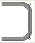
- Apex: Most bend locations are created in handrail design with the Apex. Our definition of apex is the intersection of the straight tubes as if there wasn’t a radius.
- This is demonstrated in the picture below.
- 3) Locational Orientation
-
- Designing seems to work the best if users imagine as if they are standing at a 45 degree angle to the desired creation. This way left is left and right is right. Take a minute and examine the Tri-Star (under the PickPoints] tab) to get your orientation.
Start Up
1) Start by double clicking the Bend-Tech 7x icon to start up the program.
2) Select the Railing icon ![]() in the Task Menu under the Create New section to open the Handrail Module interface. The window that opens should be labeled [Railing Design 1].
in the Task Menu under the Create New section to open the Handrail Module interface. The window that opens should be labeled [Railing Design 1].
3) For the purposes of this tutorial, click the Maximize button ![]() next to the Close button at the top right of the railing design window.
next to the Close button at the top right of the railing design window.
4) Also, for the purposes of this tutorial, zoom out significantly by spinning the wheel on your mouse so that the Tri-star is about the size of a pea in the lower left of the
display area.
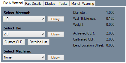
- Although it isn't necessary to choose a die, material and machine before starting, it does make it simpler for the purposes of this tutorial. The Die & Material tab is located in the upper left corner of the window.
Creating Walls
1) Select the Walls tab.
2) Select the blue New key to create the first wall with the default settings. The Create New Wall window will appear.
3) Leave all the dimensions as they are to create a wall that is 96 in.(8 ft.) high, 144 in. (12 ft.) long, and 6 in. wide. Click OK.
4) Move the cursor over to the display area. It will direct you to Select the base point of the wall.
5) Notice that the only place you'll be able to lay the wall is at the Tri-star. Place it there.
6) To create the next wall, select the same blue New key, but when the Create New Wall window opens, select the Flip Wall check box and change the direction by entering 270 in the bottom Direction field. This will change the direction in which the second wall faces by 270 degrees.
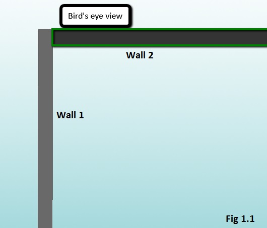
7) In the display area, the wall will appear to intersect with the previous wall. Place this new wall at the far end of the first wall. (See Fig 1.1)
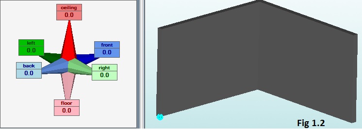
- Your screen should display the two walls as shown in Fig 1.2
Creating Steps
1) Select the Steps tab.
2) Select the blue New key to create the first set of stairs with the default settings. The Create New Step window will appear.
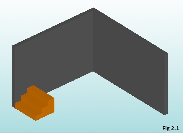
3) Leave all the dimensions as they are to create a staircase that has 3 treads (steps), is 42 in. wide with a tread width of 11 in. and riser height of 7.5 in. The only thing that will need to change is the Flip Steps check box. Check this box and click OK.
4) Place the base of the flipped steps at the front base of the first wall as shown in Fig 2.1.
- The window should show a simple three step staircase, but more steps will be created later in the tutorial.
Creating Platforms
1) Select the Platforms tab.
2) Select the blue New key to create the first platforms.
3) For our purposes, once the Create New Platform window appears, change the length of the platform from the original 42 in. to 105 in. by entering 105 in the
Length value field. It is also necessary to Flip Platform in this step.
4) Since the height of the platforms are exactly the same height as the step riser (7.5 in.) by default, place the first platform above and behind the steps in order to create
a fourth step. (Note) This will be the floor above the base floor of this design.
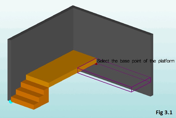
5) Then, make an additional platform along the second wall as shown in Fig 3.1. Create a new platform by changing the Width value from 42 in. to 99 in. You will also have to check the Flip Platform check box.(Note) When positioning. make sure that the platforms are along the same 3D plane. You can check by rotating the design in the display area.
Creating PickPoints and Railings
1) Select the PickPoints tab.
2) Change the value of the Ceiling field on the Tri-star to 36 in. for the purposes of this tutorial.
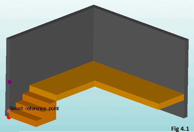
3) In order for the railing to be properly aligned with the stairway, the reference point will be the first step directly above the Tri-star in the display area. (Fig 4.1) Click the bottom step and select the Apply key. This should create a green dot 36 inches directly above it.
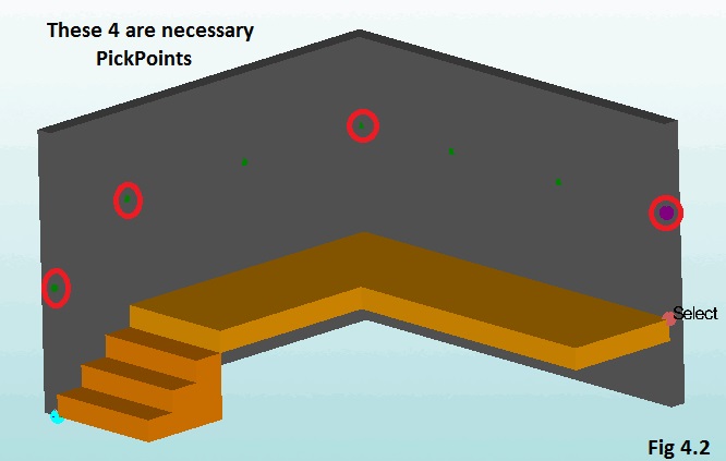
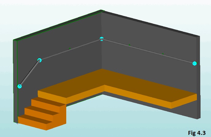
4) Continue in making at least 4 more PickPoints exactly 36 inches up from the platform created before. (Fig 4.2)
5) Clicking the Part tab will start the process of creating the length of railing.
6) Select the New Section key.
7)
