Dragon Straight Part Tutorial
Things To Know
- This tutorial will step you through the process of creating a straight design in Bend-Tech Dragon and show you the possible choices for where to take it next depending on your needs. As you walk through this tutorial, procedures are designed based on your knowledge of earlier procedures. Because of this, it is very important that you carefully step through this guide, understanding everything along the way.
Tutorial
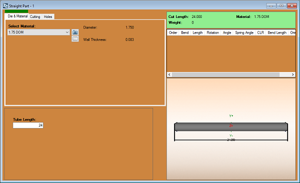
1. From the Bend-Tech Dragon start up screen, click on the Straight  button to open the straight part interface.
3. In order to start a design, select the 1.75 DOM material from the material drop down menu ![]() to the left. This material is specific to both this tutorial and corresponding tutorials including the Dragon Custom Design Tutorial and the Dragon Nesting Tutorial.
to the left. This material is specific to both this tutorial and corresponding tutorials including the Dragon Custom Design Tutorial and the Dragon Nesting Tutorial.
4. Next, select the Tube Length value field ![]() and enter the number 24. The straight tube should appear below in the display area.
and enter the number 24. The straight tube should appear below in the display area.
(Skip this image and step 5 if this view is incorrect.)
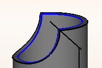
5. Now select the Coping (Fishmouth) option from both the Type of Cut (Start) ![]() and Type of Cut (End)
and Type of Cut (End) ![]() drop down menus. The copes will show in the part as seen below.
drop down menus. The copes will show in the part as seen below.
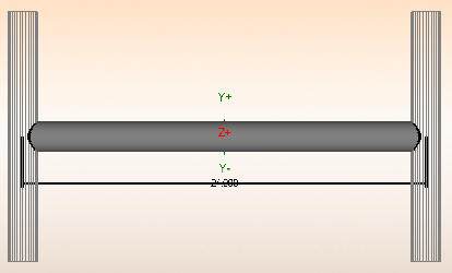
6. From here, check both Display Cross Tube ![]() checkboxes on either side of the Tube Length value field.
checkboxes on either side of the Tube Length value field.
7. Now, type 110 into both Angle  value fields. This will adjust the angle of the copes as shown in the display area.
8. Next, type 180 into the Rotation  value field beneath the Tube Length field.
9. Now, type .875 into the Offset  value field on the right hand side. This will cause the cross tube on the right side of the project to offset from the centerline by half the diameter of the tubing.
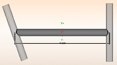
10. To finish this part, select the Miter ![]() option in the Type of Cut (Start) section and change the angle to 45 in the left Angle
option in the Type of Cut (Start) section and change the angle to 45 in the left Angle ![]() value field. The part should appear in the display screen as seen below.
value field. The part should appear in the display screen as seen below.
11. With the part finished, please save the file by clicking the Save ![]() icon from the icon menu bar at the top of the screen and name it Dragon Test1. This will be used in later tutorials including the Dragon Nesting Tutorial and Dragon Custom Design Tutorial.
icon from the icon menu bar at the top of the screen and name it Dragon Test1. This will be used in later tutorials including the Dragon Nesting Tutorial and Dragon Custom Design Tutorial.
Transferring
- After applying all of the changes to our straight part, we are free to select the desired option for transferring the part out.
- You may Transfer to Design
 for adding further geometry to the part and assigning actions before sending it to the machine, or you may Transfer to Nesting
  if you'd like the current part to be added to a nesting project without altering the part further.
- See the Dragon guide to help you decide where to go from here.
