Dragon Material Settings
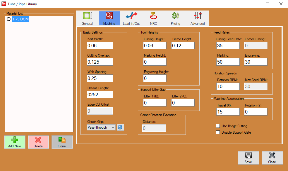
The Dragon Material Settings page is meant to show the user how the Dragon machine reacts to your different material and tooling settings. These are general guidelines meant to give you understanding about your material machine settings and how they operate both within the software and in the practical application of the Dragon machine.
Contents
Material Machine Settings Video
Standard Material Machine Settings
Hypertherm Manual Links
Hypertherm Powermax 45 XP Manual
Hypertherm Powermax 65-85 Manual
MRT Duramax Retrofit for Powermax 1000-1250-1650 Manual
MRT2 Duramax Retrofit for Powermax 600-800-900-MAX42-MAX43 Manual
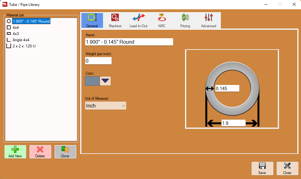
- To access the Material Settings, first select the Tube/Pipe Library from the Dragon Task Menu Screen.
General
Material Properties
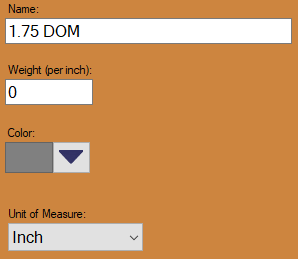
Material Name:
- This title will be used to refer to the material throughout the software. It is recommended to give each a unique, descriptive name to more easily identify each material.
Weight (per inch):
- The weight of the material per unit can be supplied here. This value is completely optional, but it will be used to calculate the total weight of the part in the part designer interfaces above the results table.
Color:
- The color of the material can be chosen using the Color button.
 This color will be used to shade the material in various areas throughout the software.
Unit of Measure:
- Parts can be measured in either inches or millimeters.
Select Shape:
- Tube material can be either Round, Square, or Rectangle. If you have our newest capabilities, you can also choose L-Channel (Angle Iron) or U-Channel.
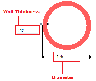
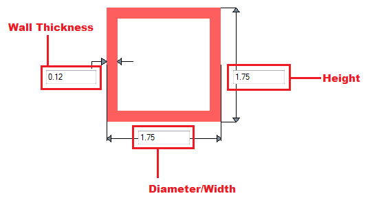
Wall Thickness, Diameter, and Height:
- Depending on the type of material chosen, there will be different dimensions that will need to be supplied. If the material is round or square, the wall thickness and diameter measurements will be required. These values will be entered into the fields on the material diagram. If the material is rectangular, the wall thickness, diameter/width, and height will need to be provided. Note: The diameter/width and height of all materials are measured from the outside edges.
Machine Settings
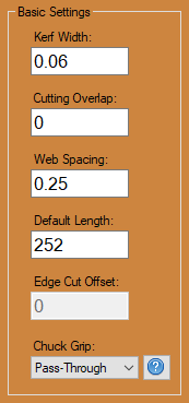
Basic Settings
-Typical Settings-
Kerf Width:
- This is the size (width) of the cutting path determined by your plasma torch. This is generally between 0.05 and 0.06 depending on your plasma torch settings and type of torch you own. Consumables that you're using and amperage can change this number considerably, so we suggest a test in order to measure the exact width.
Cutting Overlap:
- This is the amount of under travel or over travel that a cut profile will perform. This can be changed under certain circumstances. One of which would be in order to leave a certain amount of material attaching your stock tube to the cut part in order to break it off after the cut is performed.
Web Spacing:
- This is the amount of material selected to be left between any nested parts. We recommend to set this number to 0.5 to indicate that a half of an inch will be left between these parts. This will help accommodate for lead-ins and lead-outs that may require this extra space.
Default Length:
- This section indicates your default stock length of tubing typically associated with this material. Every time you select this material, your stock length of tubing in your nesting projects will default to this number. This will be input in the unit type specified in the General tab for this material.
Edge Cut Offset:
- For l-channel (angle iron) and u-channel only, this will be the distance beyond the edge of the material the lead in/out will extend when performing edge cuts.
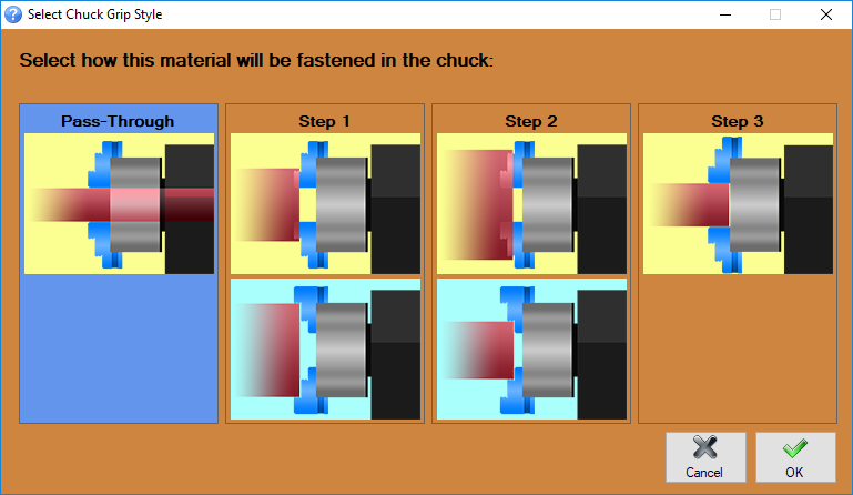
Chuck Grip:
- This setting is used to indicate whether or not you will be using the pass-through of the chuck for this material or if it will require the use of the steps on the chuck jaws. Indicating the use of any other option except for the pass-through, the software will adjust loading, flipping, repositioning, and dead zone locations based on the chuck grip selected.
- Click on the question mark icon in the software to see an image of the different steps on the chuck to help you determine what will be needed for the selected material.
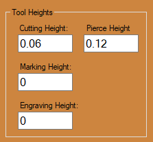
Tool Heights
-Typical Settings-
Cutting Height:
- This is the number indicating how far off the tubing the torch head will be located during cutting. This height depends on the model of torch you have as well as the material thickness. Refer to your hypertherm manual for an exact height. Links to manuals are located at the top of this page.
Marking Height:
- This number is meant to adjust the calibration values correlated to the height the marker head. (Example) If the tubing was entered as 1.75 OD, but the actual OD is 1.74, then you may enter a -.01 in this field in order to compensate for the difference in tube diameter when marking. This value should almost always be set to 0.
Engraving Height:
- This number is meant to adjust the calibration values correlated to the height the engraver head. (Example) If the tubing was entered as 1.75 OD, but the actual OD is 1.74, then you may enter a -.01 in this field in order to compensate for the difference in tube diameter when engraving. This value should almost always be set to 0.
Pierce Height:
- This number will indicate the distance that the torch will be placed off of the tubing during the piercing process of a cut. This is always 2 1/2 times the cutting height. Refer to your hypertherm manual for an exact height. Links to manuals are located at the top of this page.
Support Lifter Gap:
Not available on the Dragon A150 Series.
- This is the gap amount desired from the current lifter height. To allow for an element of increased sag in the material, enter a positive distance value. To reduce sag in the material, enter a negative value.
- Lifter 1 (B): is your standard lifter station provided with the Dragon A400 machine. Lifter 2(C): is for use if you've purchased, or designed an additional lifter station.
Corner Rotation Ext
*For square or rectangle material only
- The Corner Rotation Extension is a distance entered by the user that will cause the material to rotate before the corner radius of the material itself. This is used in cases where the wall thickness is wider than that of the extension of the corner radius on a square or rectangle material. Click the blue lettering for a visual representation of how this works.
Feed Rates
-Typical Settings-
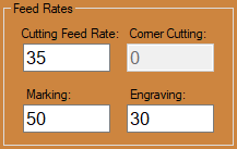
Cutting Feed Rate:
- This setting determines the rate at which the machine's torch moves in the act of performing a cut. These feed rates are dependent on your particular torch and thickness of material, so be sure to check your Hypertherm manual for exact cutting feed rates. Links to manuals are located at the top of this page.
Engraving Feed Rate:
- This is the rate at which your engraver travels along the tube. This should be set to 30 inches per minute to ensure consistent engraving.
Marking Feed Rate:
- This is the rate at which the marker travels along the tubing. This can remain at 100 inches per minute to ensure a smooth line with the marker.
Rotation Speeds:
- This Rotation Speeds setting sets the rate at which the chuck rotates during functions in a shift. This should be lowered with heavier, large OD material or in the case that you're using square or rectangle material with sharp corners. A lower rotational speed ensures that the rotational motor will not move too quickly and over-step the steps in the motor.
Machine Acceleration:
- Travel (X): The value entered here will set the acceleration for the X-axis when running jobs using this material. A lower value should be used with larger, heavier OD tubing/pipe. As an example: A typical value which could be all encompassing would be '5-10'. This would be applicable to up to 6" tubing with a 0.25" wall thickness. Many smaller OD tubing/pipe (0.75 - 1.25 OD) may allow for this value to be around '35'. Set this value to zero to apply the default located in the Factory Settings of the Machine Library (Default is 35).
- Rotation (Y): The value entered here will set the acceleration for the Y-axis when running jobs using this material. A lower value should be used with larger, heavier OD tubing/pipe. As an example: A typical value would be around '5' considering it will allow the material a smoother rotational ramp up and ramp down action. The lower the number, the longer the rotational axis takes to reach it's maximum cutting speed. Set this value to zero to apply the default located in the Factory Settings of the Machine Library (Default is 1: This value is indicating a 100% of normal value using a specific formula for determining Y-axis acceleration).
Misc Settings
Use Bridge Cutting
- When this check box in checked, any newly made nest with this material will automatically keep the torch firing as it moves from the end cut of the previous part to the start cut of the next part.
Disable Lifter Station
Not available on the Dragon A150 Series.
- When this check box is checked, the lifter station will be ignored in any new project with this material when it is sent to the Dragon machine. The lifter will not require a homing sequence, nor will it be used during the run.
Lead In/Out Defaults
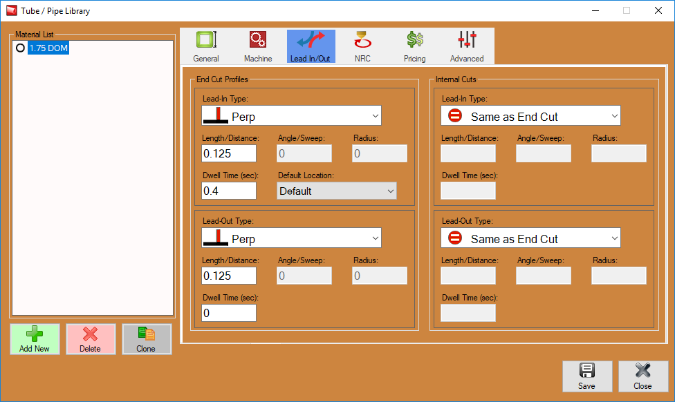
End Cut Profile Lead Defaults
- These settings are completely user specified and can vary based on the user's preference.
-Suggested Settings-
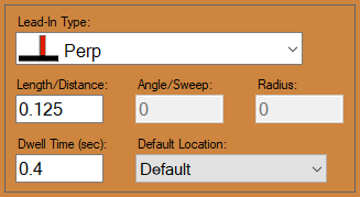
Lead In Type:
- This is where the user will select the type of lead-in ignite type that will be set to this material by default. Arc with Angle is a preferred method. This means that the torch will initiate its cut into the material at an angle which will ease into an arc and then to the intended cut profile. This is a smooth ignite type and leaves little chance for error.
Length/Distance:
- This is the length of the line that eases into the actual cut profile. We can keep this relatively short. We recommend .125 in most cases.
Dwell Time(sec):
- This indicates how long the torch will remain on one place during the pierce. This can differ based on your torch and material type and thickness. Refer to your hypertherm manual for an exact time. Links to manuals are located at the top of this page.
Angle/Sweep:
- This will be the angle at which the initial cut eases into the intended cut. We recommend a 45 degree angle for the ignite cut.
Radius:
- This is where the user will enter the radius of the arc that channels into the cut profile. We recommend keeping this at around .125 as a preference.
-Suggested Settings-
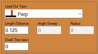
Lead Out Type:
- This is where the user will select the type of lead-out extinguish type that will be set to this material by default. Perpendicular is a preferred method. This means that the torch will extinguish its cut at a perpendicular angle after the cut profile has been performed. This is a extinguish type that leaves the cut profile smoothly at a 90 degree angle.
Length/Distance:
- This is the length of the line that eases out of the cut profile. We can keep this relatively short. We recommend .125 in most cases.
Dwell Time(sec):
- This indicates how long the torch will remain on one place during the extinguishing stage of the torch. This can be set to 0.
Angle/Sweep:
- Opposite of the ignite type section, this will be the angle at which the cut eases out of the intended cut. This will be greyed out when the perpendicular extinguish type is set as a default.
Radius:
- This is where the user will enter the radius of the arc that channels out of the cut profile. This will be greyed out when the perpendicular extinguish type is set as a default.
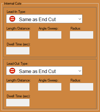
Internal Cut Lead Defaults
- All other cut lead defaults can be set like the original cut lead defaults. These are meant for all cuts other that the start and end cuts of a part.
NRC Settings
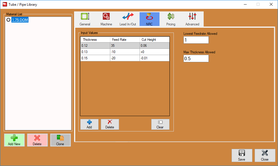
Input Values
- With NRC cutting, the further from the centerline you're cutting, the thicker the material is. This grid allows you to make fine tuning adjustments. With the default first line in the example to the right, the entire cut will have a feed rate of 35 inches per minute (ipm) and a height of .06 and a thickness of 0.12. If you find that when it gets thicker it's not cutting all the way through, then you would add an entry so that when it gets to that thickness, it will slow down or cut at a different height. In the picture shown, when the thickness of the tube is .13 or greater, the feed rate will slow down by 10(making it 25), and the height will not change. When the thickness is .15 or greater, it slows down the feed rate by 15(making it 20) and lowers the cut height -.01(making it .05).
- Inputted values will include the top line indicating your initial Thickness, Feed Rate and Cut Height and adjustments in feed rates and cut heights based on the thickness you're encountering throughout the duration of the cut. These will be inputted with (+ and -) signs to indicate the adjustment that is to be preformed.
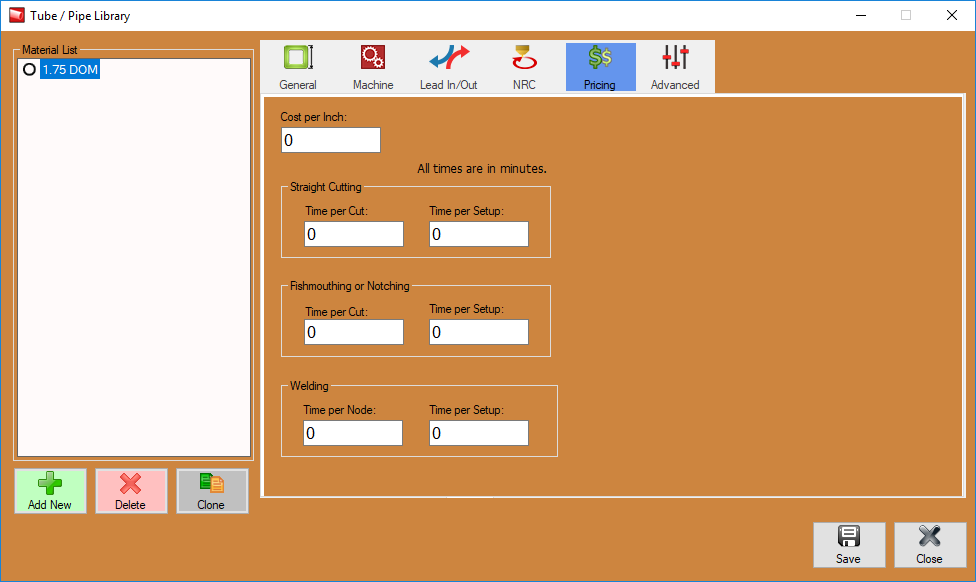
Pricing
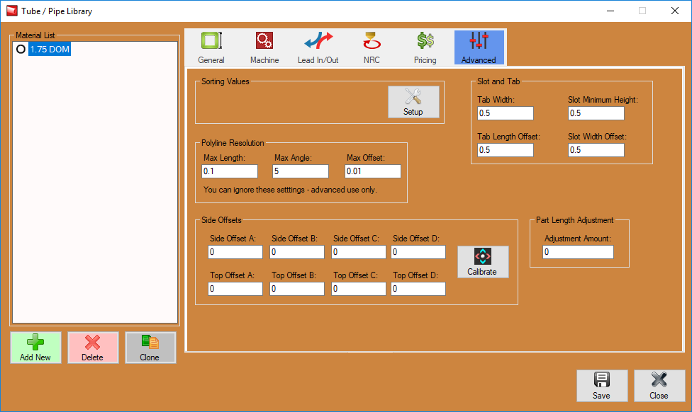
Advanced
Polyline Resolutions:
Max Length:
- This is where the user will enter the maximum length for each segment in a polyline. A segment will be ignored if it is longer than this value. If the segment is shorter, it may be combined with an adjacent segment to create a single segment.
Max Angle:
- This is where the user will enter the maximum angle between two segments in a polyline. If the angle is smaller than this value, the two segments may be combined to create a single segment.
Max Offset:
- This is where the user will enter the maximum boundary offset for a polyline. If the combination of two line segments breaches the boundary defined by this value, the features will not be combined.
