Industrial
UNDER CONSTRUCTION: THANK YOU FOR YOUR PATIENCE
"Bend-Tech Industrial comes equipped with all of the functionality available in our SE product along with the following."
Contents
Importing
"NOTE: All parts that are brought into Bend-Tech Industrial must be in either .STEP/.stp or .IGES/.igs format."
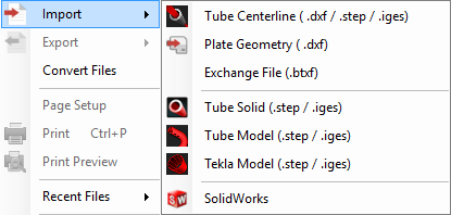
2. Choose a file to import by using the standard method. Go up to the File menu at the top left hand corner of the screen, select the Import option and choose from either Solid Model (.step/.stp), STEP (.step/.stp) or IGES (.IGES/.igs) from the list depending on which file format you'd like to import.
Defining The Part
Color Code
1. After importing a solid model, the part will appear with contoured lines, arcs and circles. These are color coded to help you to identify certain sections of the tubing.
- Yellow Lines: Indicate the centerline of the tubing.
- Blue Lines: Indicate the arcs and circles of the tubing.
- Red Lines: Indicate the straights within the length of tubing.
Material Definition
1. The Select Material: drop down menu will be grayed out until the user has fully tracked the imported part. Once the part is tracked, it will need to be assigned a material which matches its Defined: outer diameter and wall thickness.
2. The Material: section will show which material is chosen from the Select Material: drop down menu above. The Outside Diameter (OD) of the material will be shown next to the orange icon and the Material Wall Thickness will be shown next to the blue icon.
3. The Defined: section will show which material is applied to the part after importing. The detected Outside Diameter (OD) of the material will be shown next to the orange icon and the detected Material Wall Thickness will be shown next to the blue icon.
4. The number of bends detected in the part will be shown next to this icon.
Below this initial section is the tool box with four tabs labeled Part, Manual Tools, Holes & Cutouts and Saddles.
Part
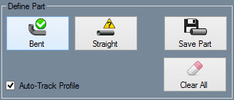
Define Part
- This section contains the general options for defining a part automatically.
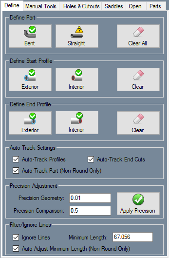
1. For any imported part containing a bend, click on the "Bent" button followed by a single arc/circle (Blue Line) at the end of the tubing in order to track the part automatically. The part will become a 3-D model with material applied to it when it has been successfully tracked.
2. For any imported straight part, click on the "Straight" button followed by a straight side of the tubing (Red Line), then an arc/circle (Blue Line) at the end of the tubing. NOTE: You may have to The part will become a 3-D model with material applied to it when it has been successfully tracked.
3. To clear your progress and revert the part back to its original solid model form, click the "Clear" button. A window will appear to ensure that you want to confirm the changes.
Define Start Profile
- This section contains the options for defining the interior and exterior edge on the start profile of the tubing.
1. Click on the "Exterior" button followed by the outer arc/circle (Blue Line) at the START of the tubing. NOTE: If the circle at the edge of the tubing is split into smaller arcs, you may have to select multiple arcs along the same path in order to define this exterior circle. If it is Red, it is not complete. If it is Green, the circle has been defined.
2. Click on the "Interior" button followed by the inner arc/circle (Blue Line) at the START of the tubing. NOTE: If the circle at the edge of the tubing is split into smaller arcs, you may have to select multiple arcs along the same path in order to define this interior circle. If it is Red, it is not complete. If it is Green, the circle has been defined.
3. To clear your progress and revert the part back to before the start profile was defined, click the "Clear" button. A window will appear to ensure that you want to confirm the changes.
 - This section contains the options for defining the interior and exterior edge on the end profile of the tubing.
1. Click on the "Exterior" button followed by the outer arc/circle (Blue Line) at the END of the tubing. NOTE: If the circle at the edge of the tubing is split into smaller arcs, you may have to select multiple arcs along the same path in order to define this exterior circle. If it is Red, it is not complete. If it is Green, the circle has been defined.
2. Click on the "Interior" button followed by the inner arc/circle (Blue Line) at the END of the tubing. NOTE: If the circle at the edge of the tubing is split into smaller arcs, you may have to select multiple arcs along the same path in order to define this interior circle. If it is Red, it is not complete. If it is Green, the circle has been defined.
3. To clear your progress and revert the part back to before the end profile was defined, click the "Clear" button. A window will appear to ensure that you want to confirm the changes.


