Main
Bend-Tech 7x Wiki :: Assembly :: Main
Parts List
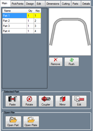
The Part List is a list of all parts that have been added to the current Assembly project. Select a part in the list to view a preview of it. The Qty (Quantity) column displays the number of times that the part is used in the current Assembly project and the Key column states the key number given to the part to identify it. To remove a part from the list, click the Remove button. ![]() To remove all unused parts from the Master Part List, click the Flush button.
To remove all unused parts from the Master Part List, click the Flush button. ![]()
Selected Part
Paste
To paste a copy of a part from the parts list into the assembly, first select a part. Then click the Paste button. ![]() The selected part will then be attached to the cursor. Select a PickPoint in the display to place the part upon.
The selected part will then be attached to the cursor. Select a PickPoint in the display to place the part upon.
Rotate
Creates a rotated version of an existing part which can be placed into the Assembly project.
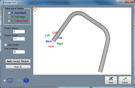
Select a part from the Part List and click the Rotate button. ![]()
Select an axis to rotate the part around in the Select Axis of Rotation area.
Enter an amount to rotate the part in the Rotation Amount field, or left click on the part and drag the cursor left or right to rotate the part.
Enter a value in the Snap Increment field and check the Snap Rotation checkbox in order to use snap rotation. Snap rotation will rotate a part by the amount in the Snap Increment field when the part is rotated using the left mouse button.
To change the amount that the part is rotated when not using snap rotation, enter an amount in the Rotation Speed field. By default, the rotation speed will be 1, meaning the part will be rotated one degree at a time. Entering a decimal will allow the part to be rotated by smaller increments. Whenever you rotate a part in a certain axis, you must click the Apply Current Rotation button before rotating the part in another axis.
To reset the orientation of the part, click the Reset All button.
After all rotations have been applied, click the OK button.
Coupler
Allows the user to move the coupler (the anchor point of the part).
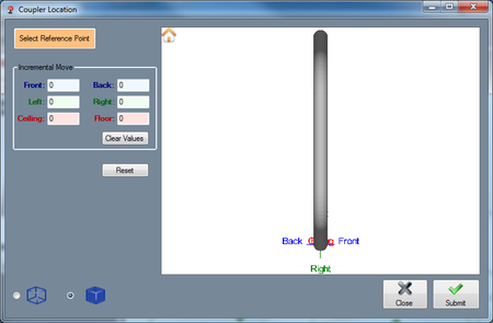
Select a part in the Part List and click the Coupler button. ![]() The Coupler Location window will appear.
The Coupler Location window will appear.
To set the reference point, click the Select Reference Point and click a PickPoint in the Coupler Location window display area.
To move the anchor point, use the Incremental Move fields and enter movement values.
To set all fields to 0 in the Incremental Move area, click the Clear Values button.
Click the Reset button to reset the coupler to its original location.
To toggle between viewing a shaded and wireframe version of the part, use the display mode options.
Mirror
Creates a mirrored version of an existing part which can be placed into the Assembly project.
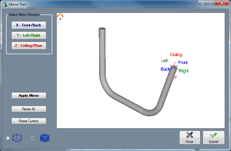
Select a part from the Part List and click the Mirror button. ![]() The Mirror Part window will appear.
The Mirror Part window will appear.
In the Select Mirror Direction area, select an axis to mirror the part across. After a part has been mirrored, you must click Apply Mirror before mirroring the part again.
Click Reset Current to revert the part to the last time you clicked the Apply Mirror button.
Click Reset All to reset the part to its original orientation. Click the home button to set the display to the home view. Click OK to create the mirrored part.
To toggle between viewing a shaded and wireframe version of the part, use the display mode options.
Edit
To edit a plate part in the Plate design interface, first select a plate part from the Part List, then click the Edit button. ![]()
Open File
To open a part or plate part and use it in the current assembly design, click the Open Part ![]() or Open Plate button
or Open Plate button ![]() and select a part/plate file. The part will then be added to the Part List and attached to the cursor where it can be placed by clicking on a PickPoint in the part display.
and select a part/plate file. The part will then be added to the Part List and attached to the cursor where it can be placed by clicking on a PickPoint in the part display.


