Rules of Custom 3D
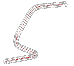
1) Always follow the center line of the material. This is in comparison to outside or inside of the material. The following diagram shows the red line as the center of the material:
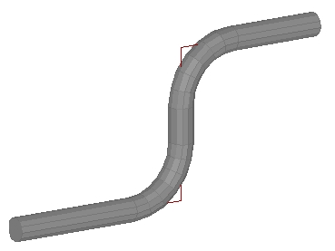
2) This interface uses the Apex of the bends. As shown in the following diagram, the Apex is the intersections of the red lines.
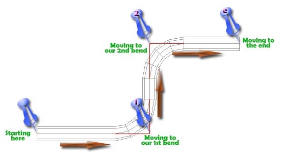
3) You are sequentially moving along the part. You are starting on one end of the tube and are moving from feature to feature until you reach the other end.
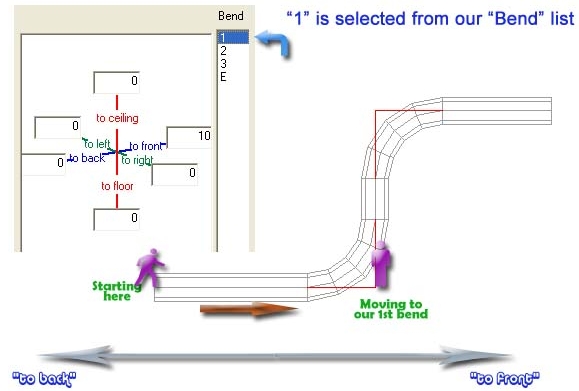
4) You are entering the distance(s) to the next feature. When you selected 1 from the bend list, this means you are standing at the one end of the tube, heading to the first bend. When you select 2 from the bend list, you are located at bend number #1 and entering in the distance to bend #2
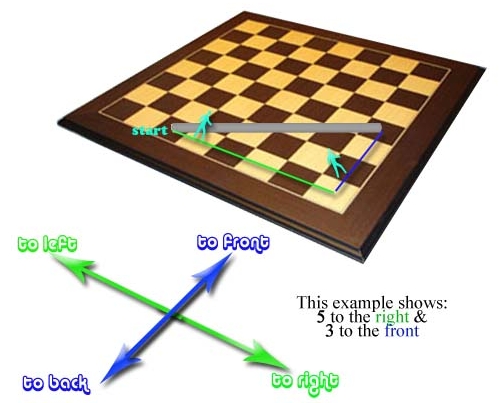
5) Think of the directions as a 3d chess board. You are not entering in angles and distances, you are combining directions and lengths to come up with a location.
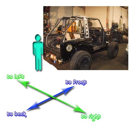
6) Imagine yourself standing behind the vehicle. This is the case if your object has a front, back, left and so on. The reason for this is to keep the left side such it is left as you face forward. If you start entering the world of assembly with Bend-Tech PRO or SE this is very important.
