Misc
Bend-Tech 7x Wiki :: Assembly :: Edit :: Misc
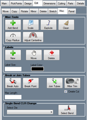
Misc Tools
Add Bend
To add a bend to a preexisting part, click the Add Bend button ![]() and select a straight length of a part by clicking on it to choose a location for the bend. The bend will be placed at the mid point of the selected part length.
and select a straight length of a part by clicking on it to choose a location for the bend. The bend will be placed at the mid point of the selected part length.
Enter the offset distance between the part and the bend. Then click the OK button to place the bend. Whichever die is currently selected in the Assembly die menu will be used for this bend.
Scale
To scale the size of parts, material, or bend radii, click the Scale button. ![]()
In the scale window, scale values for each of these features can be supplied. Provide a percentage value to either increase or decrease the scale of a feature. See image below for an example.
Explode
Exploding an Assembly will move all parts away from each other so that they can be viewed separately.
First, click the Explode button. ![]()
The click on a PickPoint to set the base point for the assembly, and enter an explode factor to explode an Assembly project. Larger numbers will create greater distances between the parts. Click the Explode button to reset the assembly back to the normal display.
Clean
Click the Clean button ![]() to clear the assembly of any zero length tubes that may be in the assembly design.
to clear the assembly of any zero length tubes that may be in the assembly design.
Copy Radius
Click the Copy Radius button ![]() to copy the radius of one bend to another.
to copy the radius of one bend to another.
First, select the bend with the radius that you want to copy. Next, select the bend that the copied radius will be applied to.
Adjust Centerline
Click the Adjust Centerline button ![]() to change how the part measurements are interpreted. In the part designers, parts are assumed to be based on centerline. This tool allows the current part dimensions to be from the inside or outside of the tube instead.
to change how the part measurements are interpreted. In the part designers, parts are assumed to be based on centerline. This tool allows the current part dimensions to be from the inside or outside of the tube instead.
After clicking the button, select a part in the display to adjust it.
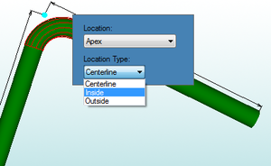
To change the Location and/or Location Type for a bend, first select the bend by clicking on it in the part display. A menu will appear where the location and location types can be adjusted. Click on either of the drop down menus to choose new options.
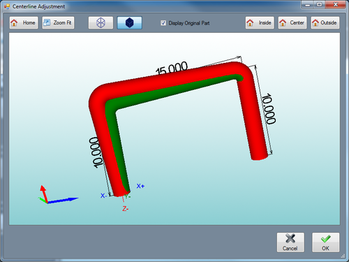
Once a new location or location type has been chosen, a red preview reflecting the location changes will appear. The original part will be shown in green (if the Display Original Part is checked).
Click the Home button ![]() to set the part preview to the default location and orientation.
to set the part preview to the default location and orientation.
Click the Zoom Fit button ![]() to zoom all the way in on the current view of the 3D part display and fit it to the display frame.
to zoom all the way in on the current view of the 3D part display and fit it to the display frame.
The part model can be shown in either wire frame or as a solid shaded model. Click on the wireframe button ![]() to show the model in wireframe. Click on the shaded button
to show the model in wireframe. Click on the shaded button ![]() to show the model as a shaded part.
to show the model as a shaded part.
Check the box next to Display Original Part to have the original part preview shown in the adjust centerline interface after changes are made to the locations.
Click the Inside button ![]() to set the locations for all of the bends to inside.
to set the locations for all of the bends to inside.
Click the Center button ![]() to set the locations for all of the bends back to centerline.
to set the locations for all of the bends back to centerline.
Click the Outside button ![]() to set the locations for all of the bends to outside.
to set the locations for all of the bends to outside.
Click the OK button ![]() to take the location and location type adjustments and apply them to the current part design.
to take the location and location type adjustments and apply them to the current part design.
Labels
To place labels on the current assembly design, first click the New button ![]() and select a location for the label by clicking on a PickPoint. Next, enter the label text and click OK.
and select a location for the label by clicking on a PickPoint. Next, enter the label text and click OK.
The size of the label font is determined by the Label Size value (larger values result in larger labels and vice versa). To change the size, enter a new value in this field. The color of the labels is determined by the Label Color button. To change the color, click this button and select a new color.
To move a label, click the Move button ![]() and select a new PickPoint to place the label in the new location.
and select a new PickPoint to place the label in the new location.
To delete a label, click the Delete button ![]() and click on a label.
and click on a label.
Break or Join Tubes
Click the Break Auto button ![]() to
to
Click the Break Point button ![]() to place a break point on a certain part. Break points will define where the part will be separated. After clicking this button, select which part will be broken by clicking on it in the display area. Last, select the PickPoint where the break will occur.
to place a break point on a certain part. Break points will define where the part will be separated. After clicking this button, select which part will be broken by clicking on it in the display area. Last, select the PickPoint where the break will occur.
Click the Join Tubes button ![]() to connect two tubes together. First, select the first part to join, and then select the other part that will be joined to it.
to connect two tubes together. First, select the first part to join, and then select the other part that will be joined to it.
Click the Miter Trim button ![]() to
to
Single Bend CLR Change
To adjust the CLR of a single bend, first select a die in the Select Die menu in the Single Bend CLR Change area. Next click the Select Bend button ![]() and click on a bend to apply the selected die to it.
and click on a bend to apply the selected die to it.


