Bend Order Tutorial
Bend Order
- While creating any type of single part, the bend order can be edited and a simple simulation of the bending process can be viewed. This tutorial will walk the user through some of the functions available in the Bend Order menu.
- First, a single part design needs to completed before the simulation can be accessed. For this tutorial, we will be using the part that was created in the Template Tutorial above. Complete that tutorial if you would like to follow along while stepping through this one.
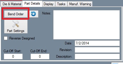
- Select the Tools tab in the tabbed section in the top left corner of the part design window. In this tab, select the "Bend Order" button.
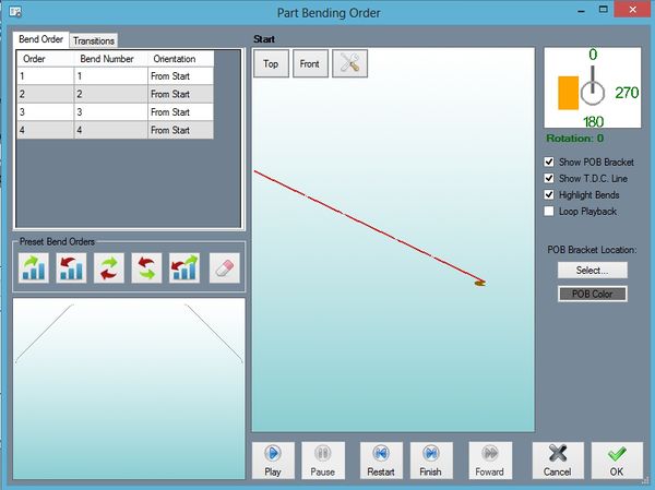
- The Part Bending Order window will open. The right side of this window is mostly occupied by the simulation frame along with the control buttons. The left side of the window shows the Bend Order and Transitions tabs with a 3D part display frame in the bottom corner. In between these windows, there are bending order and animation setting options.
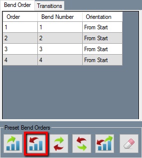
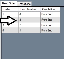
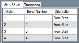
- First, we will adjust the bend order. If the Bend Order tab is not already selected, select it. Below "Preset Bend Orders", select the "Reversed" button. Doing so will completely reverse the entire bending number order and orientation of each bend as shown below.
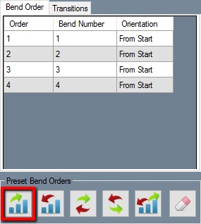
- Select the "Normal" button to set the bend order back to the standard order.
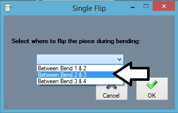
- Below "Preset Bend Orders", select the "Normal Flip" button. Once selected, you will be prompted to choose which bends the flip will occur between. Click the drop down menu and select Between Bend 2 & 3. The bend order will now completely reverse order and orientation in between the bends chosen.
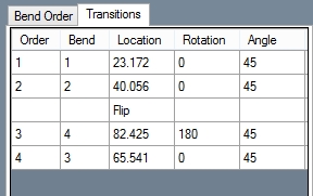
- Select the Transitions tab. Within this tab, a chart containing each bend and flips is shown. Clicking on any of the location, rotation, or angle cells will set the part preview to the chosen movement.
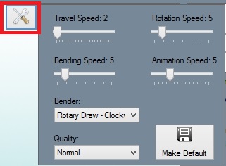
- In the Simulation Settings section, the speed settings for the simulation can be adjusted. These can be changed by clicking on and dragging the pointers below each setting.
- Adjust each of these so they are close to the values shown below.
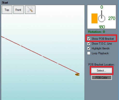
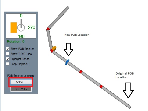
- On the far right side of the window, make sure the check box next to Show POB Bracket is checked. Click the "Select" button and click on the start end of the tube as shown below.
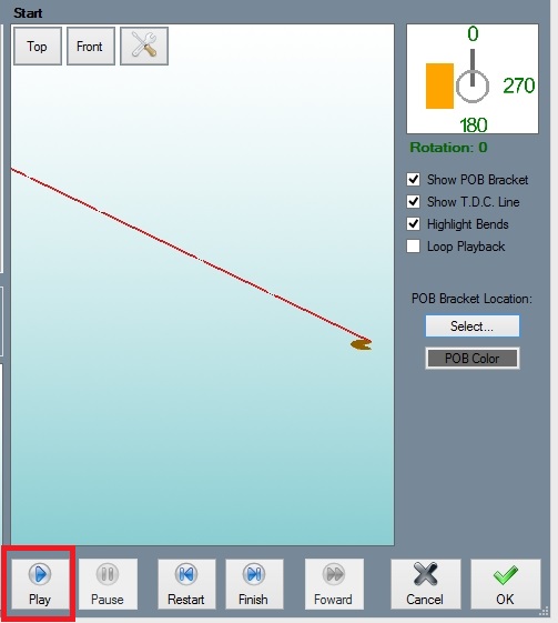
- Select the "Play" button. A simulation of the part being bend will be shown in the simulation frame. Notice that the part flips between the bends we chose while manipulating the bend order earlier on.
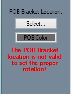
- Notice that a warning message will appear below the POB Bracket selection area right after the third bend.
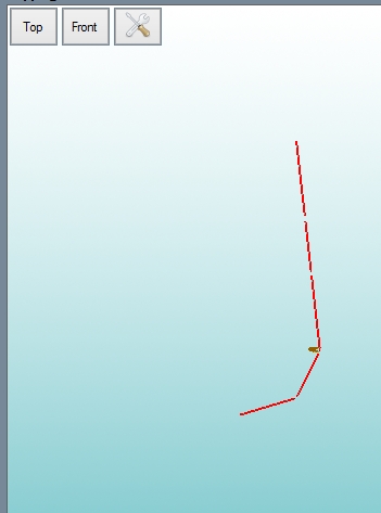
- To fix this, we need to adjust the location of the POB bracket before the simulation reaches the fourth bend. Select the "Restart" button and then click "Play" again. Let the simulation run through the second bend. Click the "Pause" button before the third and fourth bends, right after the part flips over (shown below).
- Once the simulation is paused, click the "Select" button and click on the location shown below. The POB bracket will be moved to the chosen spot on the tube. Select the "Play" button again to proceed with the simulation. The POB bracket will now function properly.
- The "Print" and "Save" buttons can be used to either print the current view of the part in the simulation or save the current view as an image file.
- Select the "OK" button to save and exit the bend order menu.
