Flat Layout
Bend-Tech 7x Wiki :: Single Part -Interface/General Functions :: Flat Layout
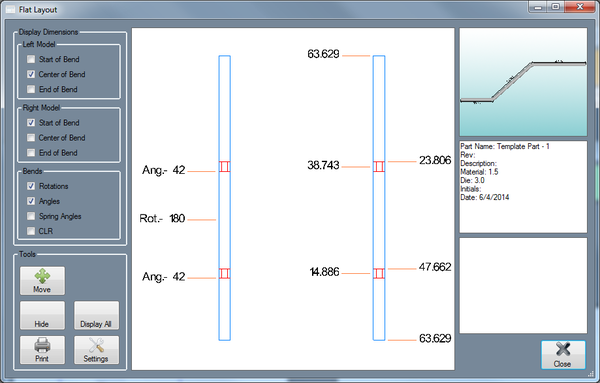
On the left side of the window is occupied by the Display Dimensions section. Under Left/Right Model, the left and right models each have the option to display the start, center, or end of the bends. Check the box next to the desired option(s) to have them displayed on the part display. Under Bends, check Rotations, Angles, and/or CLR to have them displayed on the part display. Rotations and angles will only be shown on the right model while CLR is only shown on the left.
Below the Display Dimensions section is the Tools section. Click the Move button ![]() to change the location of any of the displayed dimensions. Once the button has been clicked, each dimension will have a blue dot next to it. Click on the dot and move the cursor to a new location and click again to place the dimension. Click the Hide button
to change the location of any of the displayed dimensions. Once the button has been clicked, each dimension will have a blue dot next to it. Click on the dot and move the cursor to a new location and click again to place the dimension. Click the Hide button ![]() to remove a dimension from the display. Once clicked, each dimension will have a blue dot next to it. Click on the dimension to remove it. Click the Display All button
to remove a dimension from the display. Once clicked, each dimension will have a blue dot next to it. Click on the dimension to remove it. Click the Display All button ![]() to have all dimensions that were previously suppressed displayed again. Click the Print button to print the current view of the flat layout, 3D model, part information, and notes.
to have all dimensions that were previously suppressed displayed again. Click the Print button to print the current view of the flat layout, 3D model, part information, and notes.
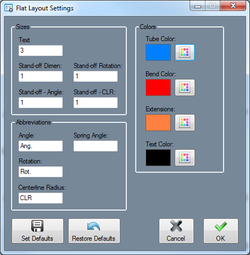
There is also a Settings button. ![]() Click to access the settings for the flat layout display. Under Flat Layout - Sizes, the text size along with the stand-off (distance between dimension lines and the part surface) values for dimensions, angle, rotation, and CLR can be adjusted. Under Flat Layout - Abbreviations, the abbreviations for angle, rotation, and centerline radius can be changed. To change, enter a new abbreviation into the field next to any of the options. These abbreviations will only be applied to the flat layout display. Under Flat Layout - Colors, the colors of the tube, bends, extensions, and text can be changed. To change color of any of these features, click the button and choose a new color in the Color menu. The buttons will display the currently selected color of the feature. Click the 'Set Defaults' button to set the current selected sizes, colors, and abbreviation as the defaults in the Global Settings (These can be accessed through the Tools menu in Options). Click the 'Restore Defaults' button to reset the settings back to the original default settings.
Click to access the settings for the flat layout display. Under Flat Layout - Sizes, the text size along with the stand-off (distance between dimension lines and the part surface) values for dimensions, angle, rotation, and CLR can be adjusted. Under Flat Layout - Abbreviations, the abbreviations for angle, rotation, and centerline radius can be changed. To change, enter a new abbreviation into the field next to any of the options. These abbreviations will only be applied to the flat layout display. Under Flat Layout - Colors, the colors of the tube, bends, extensions, and text can be changed. To change color of any of these features, click the button and choose a new color in the Color menu. The buttons will display the currently selected color of the feature. Click the 'Set Defaults' button to set the current selected sizes, colors, and abbreviation as the defaults in the Global Settings (These can be accessed through the Tools menu in Options). Click the 'Restore Defaults' button to reset the settings back to the original default settings.
On the right side of the part display, a small 3D part preview is displayed along with some basic information of the part and any notes that were added to the part. Click the Close button to close the Flay Layout window.

