Dragon A400 Side Offsets Calibration
Dragon A400 Side Offsets Calibration
This calibration is still in its testing phase and will be ready for use in Dragon A400 version 1.07.13.
This calibration is meant for Dragon A400 users experiencing differences in cutting height due to front gate offset issues while running square and rectangular tubing only.
1.
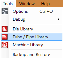
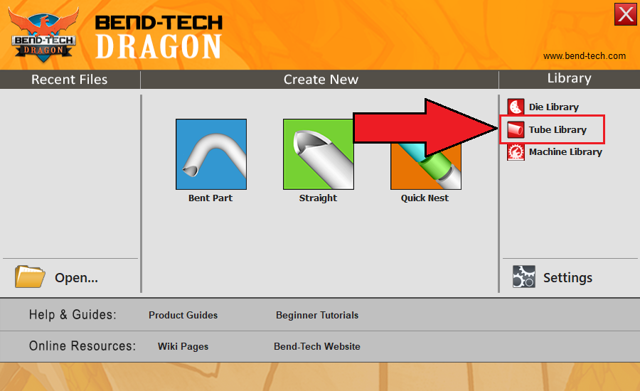
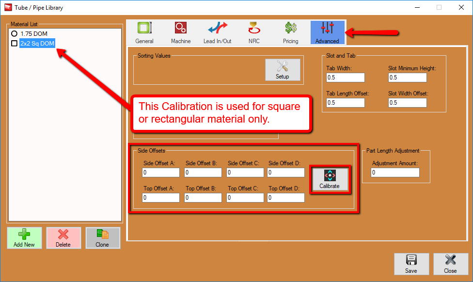
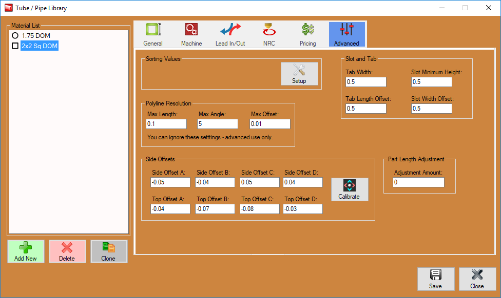
If you require a way to calibrate based on your tubing, the option is here for you located in the Tube/Pipe Library under the Advanced tab. You will have to select a square or rectangular tubing from the material list in order to change to the Advanced tab.
2.
In the Advanced tab, select the Calibrate option under the Side Offsets section at the bottom of the window.
3.
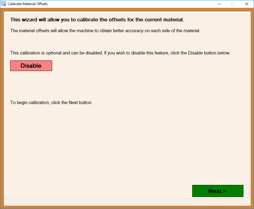
The first screen is available to Disable any previously entered material side offsets (as an option) before continuing with the calibration. click Next to start the calibration process.
4.
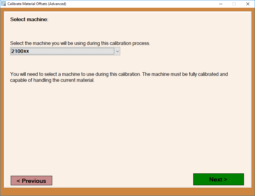
On this screen, you will be prompted to select your machine (usually named for its serial number) before continuing. Once the proper machine is selected, click the Next button.
5.
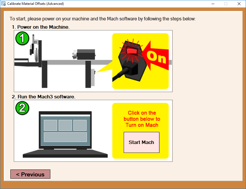
Now, ensure that your machine is turned on and click the Start Mach button on the screen to turn on the Mach 3 software, or, in the case that it is already turned on, the calibration screen will acknowledge this and continue to the next step in the calibration process.
6.
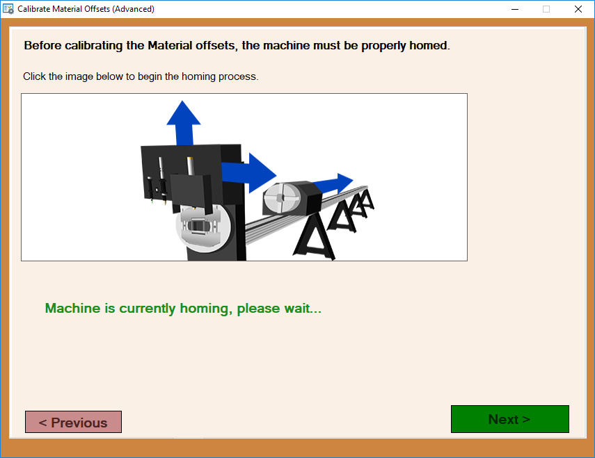
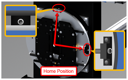
The calibration window will appear and instruct you to home your machine before continuing. Once it is completely home, the green lettering will disappear and you are free to click the Next button. IMPORTANT: Make sure the front gate is positioned to its HOME position before continuing.
7.
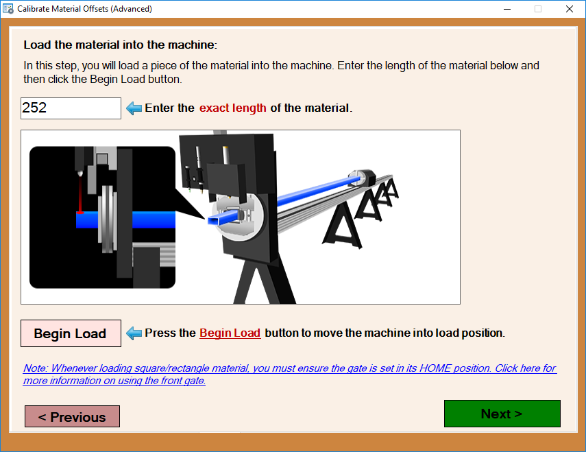
Now, you will be prompted to indicate the length of the tubing by entering it into the provided value field, then click the Begin Load button to bring the chuck trolley to its load position for this length tube. Proceed to load the material and click the Next button once you've done so.
8.
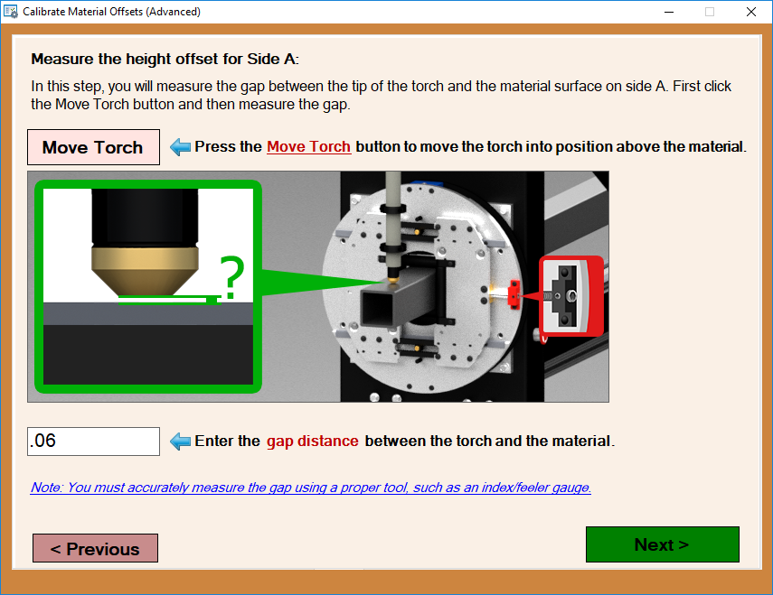
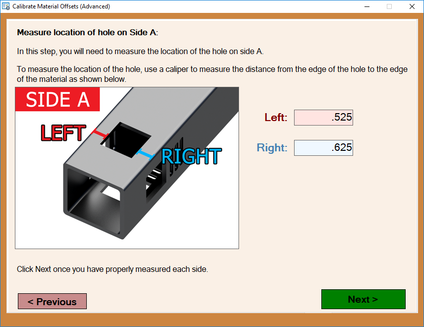
Obtain a feeler gauge for the following steps. For our purposes, we will refer to this top side of the material as (Side A). Select the Move Torch button in this window and proceed to using the feeler gauge to judge the exact height of the torch tip from the top dead center of the material's surface. Indicate the gap distance in the value field provided and select the Next button.
The torch should now raise and the chuck will rotate exactly 90 degrees for use on the next step.
9.
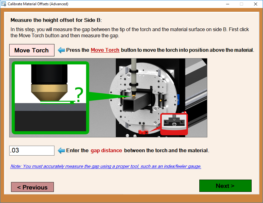
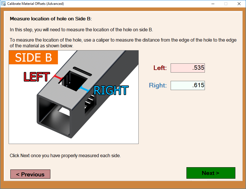
In this step the gate should be rotated to the orientation shown in the picture (90 degrees from home). You will then take a new reading with the feeler gauge on this next face of the tubing (Side B). The reading should be entered into the value field below. Then, click the Next button.
The torch should now raise and the chuck will rotate exactly 90 degrees for use on the next step.
10.
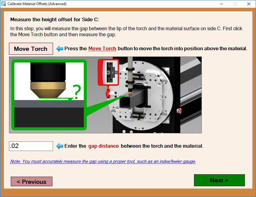
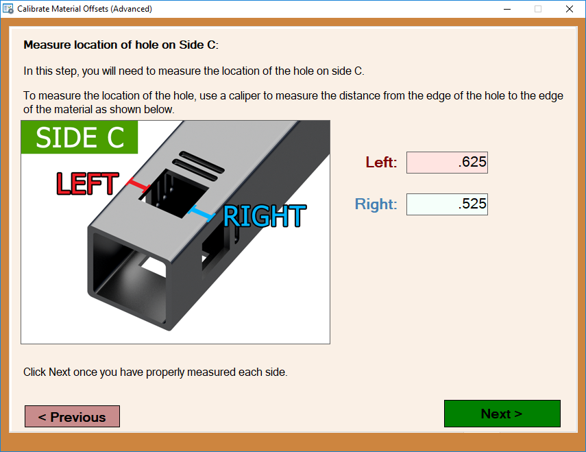
180 degrees from home now you will take another reading from side 3 of the tubing (Side C). The reading should be entered into the value field below. Then, click the Next button.
The torch should now raise and the chuck will rotate exactly 90 degrees for use on the next step.
11.
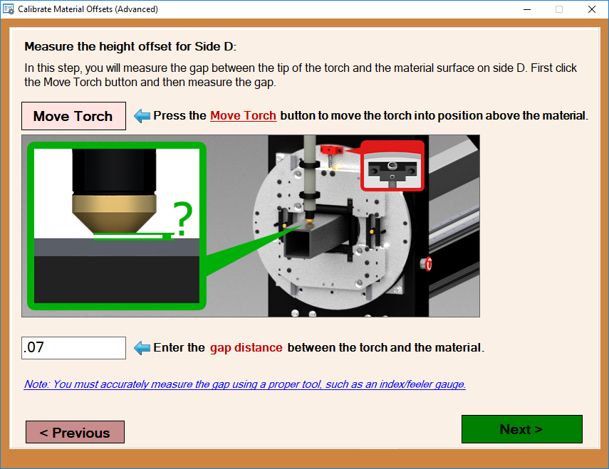
270 degrees from home now you will take a final feeler gauge reading and input the distance once again for (Side D). Then, click the Next button.
The torch should now raise and the chuck will rotate exactly 90 degrees for use on the next step.
12.
Now, with the gate rotated to its home position once again (Side A), reset the dial indicator located at the top side of the material and zero it out here and enter 0 in the input field before continuing to the next step.
13. Rotate the tube 90 degrees as shown in the picture making sure not to move the dial indicator and take a new reading on this next face of the tubing. The reading should be entered into the value field below. (This can be a positive or negative value).
14. Rotate the tubing an additional 90 degrees (180 from home now) and take another reading from the dial indicator on side 3 of the tubing. The reading should be entered into the value field below. (This can be a positive or negative value).
15. Rotate the tube a final 90 degrees and input the distance read from the dial indicator once again. (This can be a positive or negative value).
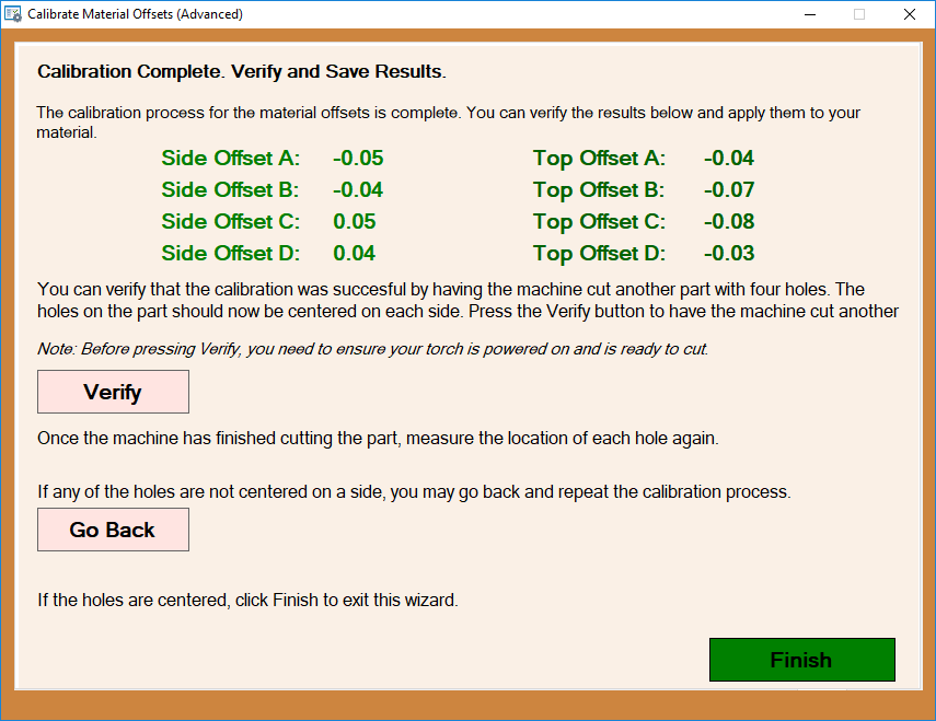
16. This screen will show your newly complete calibration values for the material and will be applied to any new project made with this material.
