Difference between revisions of "Transitions"
| Line 1: | Line 1: | ||
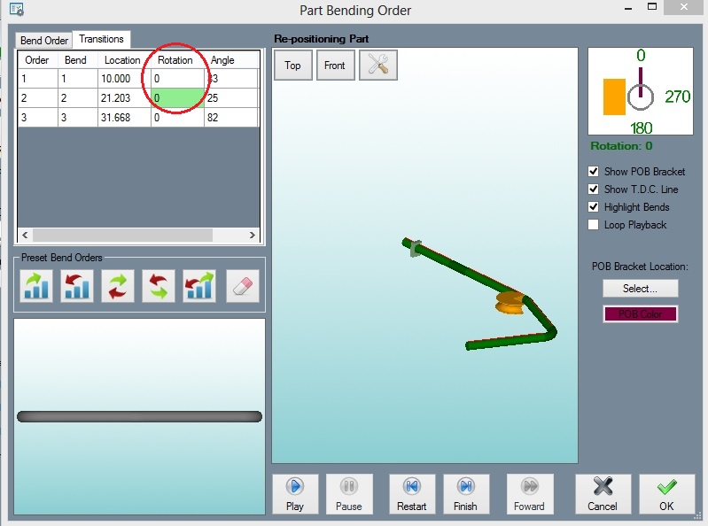
The '''"Transitions"''' tab is located at the top left of the simulation interface and is circled in the following image: | The '''"Transitions"''' tab is located at the top left of the simulation interface and is circled in the following image: | ||
| − | Transitions1. | + | [[File:Transitions1.jpg]] |
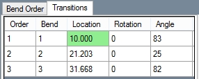
The fields in the "Location", "Rotation", and "Angle" columns can be clicked on and the simulation viewer will display a still image of what is happening at that point of the part creation. | The fields in the "Location", "Rotation", and "Angle" columns can be clicked on and the simulation viewer will display a still image of what is happening at that point of the part creation. | ||
| Line 9: | Line 9: | ||
NOTE: The field that is shaded green shows what is currently being displayed in the simulation and is not an indication of what you've selected to show the still frame of. The event you select will have a dotted line around it in the results field. | NOTE: The field that is shaded green shows what is currently being displayed in the simulation and is not an indication of what you've selected to show the still frame of. The event you select will have a dotted line around it in the results field. | ||
| − | Transitions2. | + | [[File:Transitions2.jpg]] |
'''"Location"''' will display the straight (or linear) movement of a part through the die. For example, clicking on the '''"21"''' under the '''"Location"''' column will display the following: | '''"Location"''' will display the straight (or linear) movement of a part through the die. For example, clicking on the '''"21"''' under the '''"Location"''' column will display the following: | ||
| − | Transitions3. | + | [[File:Transitions3.jpg]] |
'''"Rotation"''' will display the point where a part is to be rotated while in the bender. If a bend has no rotation, clicking on them will display nothing. This example shows the rotation in the second bend: | '''"Rotation"''' will display the point where a part is to be rotated while in the bender. If a bend has no rotation, clicking on them will display nothing. This example shows the rotation in the second bend: | ||
| − | Transitions4. | + | [[File:Transitions4.jpg]] |
'''"Angle"''' will display the part before and after the bend (angle). This example shows the first bend: | '''"Angle"''' will display the part before and after the bend (angle). This example shows the first bend: | ||
| − | Transitions5. | + | [[File:Transitions5.jpg]] |
Revision as of 13:19, 9 June 2014
The "Transitions" tab is located at the top left of the simulation interface and is circled in the following image:
The fields in the "Location", "Rotation", and "Angle" columns can be clicked on and the simulation viewer will display a still image of what is happening at that point of the part creation.
The wire frame in the image shows where the part was before the event you click on happened, and the solid part shows the after (see examples below).
NOTE: The field that is shaded green shows what is currently being displayed in the simulation and is not an indication of what you've selected to show the still frame of. The event you select will have a dotted line around it in the results field.
"Location" will display the straight (or linear) movement of a part through the die. For example, clicking on the "21" under the "Location" column will display the following:
"Rotation" will display the point where a part is to be rotated while in the bender. If a bend has no rotation, clicking on them will display nothing. This example shows the rotation in the second bend:
"Angle" will display the part before and after the bend (angle). This example shows the first bend:


