Harpoon 3D Tutorial
Bend-Tech 7x Wiki :: Harpoon 3D
Note: This tutorial will use inches as the measurement units.
Part Design
- This tutorial will begin by showing how to create a part designed with "Harpoon 3D".
- While designing a part in the Harpoon 3D designer, the material and die are chosen and the part is designed by clicking and dragging the Tri-Star ends from the harpoon tool or entering values into the value fields.(please note that features can be easily altered to fit the user's needs after they are placed in the display area.)
- "If you're not familiar with this interface, it is suggested that you visit the Handrail Module page for better understanding of the basics."
Things To Know
- "This tutorial is designed to walk the user through creating a part in a 3D environment. As you go through this tutorial, later procedures will assume that you understand all earlier procedures. Because of this, it is very important that you carefully step through this guide, understanding everything along the way and following all steps in order."
- "A few key items need to be addressed before starting the step-by-step instructions of this tutorial. It is very important for Bend-Tech users to completely understand these items:"
- 1) PickPoints
- PICKPOINTS ARE NOT USED IN HARPOON 3D; ONLY BENDS. The Harpoon 3D part of the software is largely run in full 3D. Because a computer screen is only 2D, there is an unlimited amount of depth behind and in front of the cursor. For this reason, users will have to focus more on the direction in which they will be pulling the Tri-Star ends instead of focusing on PickPoints.
- There is only 1 PickPoint in Harpoon 3D; the initial (0,0,0) point is an automatic point that resides at the center of the Tri-Star. The Tri-Star is our directional definition locator.
- 2) Center Line & Apex
-
- Center Line: In the handrail design environment we are working exclusively with the "center-line" of a part, as compared to the inside or outside.
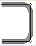
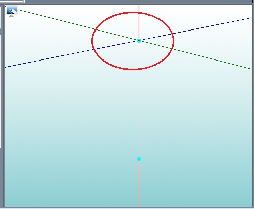
- Apex: Most bend locations are created in handrail design with the "Apex". Our definition of apex is the intersection of the straight tubes as if there wasn’t a radius.
- This is demonstrated in the picture below.
- 3) Locational Orientation
-
- Designing seems to work the best if users imagine as if they are standing at a 45 degree angle to the desired creation. This way left is left and right is right. (Only after selecting Material & Die) Take a minute and examine the Tri-Star to get your orientation.
Start Up
1) Start by double clicking the "Bend-Tech 7x" icon to start up the program.2) Select the "Harpoon 3D" icon ![]() in the Task Menu under the "Create New" section to open the Harpoon 3D interface. The window that opens should be labeled [Harpoon 3D Part - 1].
in the Task Menu under the "Create New" section to open the Harpoon 3D interface. The window that opens should be labeled [Harpoon 3D Part - 1].
3) For the purposes of this tutorial, click the "Maximize" button ![]() at the top right of the Harpoon 3D design window.
at the top right of the Harpoon 3D design window.
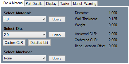
4) For the purposes of this tutorial. The "Die & Material" tab is located in the upper left corner of the window. Select the "1.00 Material" and "2.0 Die" as seen here.
Creating the Part
- 1. To create the first length of the part, type "20" into the "Ceiling" entry field. Notice the change in the length of the part in the display area to the right.
Tip: While manually dragging the part length is convenient, it can be a bit tricky to get exact measurements. To define a part length you can also use any of these alternative methods:
1. Type the length into the entry field that matches the harpoon point (In this case, the red entry field).
2. Click the harpoon point (In this case, the red harpoon point) and directly type in the length using the keyboard.
Step 6
 Next, the first bend will be added to the part. Click the add bend button.
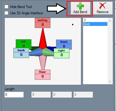
The add bend button is located near the upper left corner, as shown in the image to the right. Once this button is clicked, a bend will be added to the part.
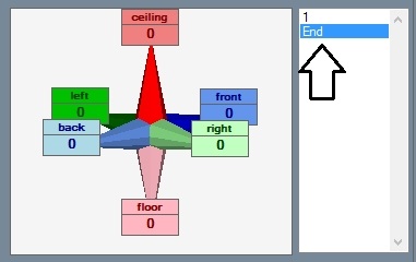
In the bend list below, there will be a 1 and an end listed. The 1 represents the length that was added in step 5 and the end represents the bend/length that will be created in this step.
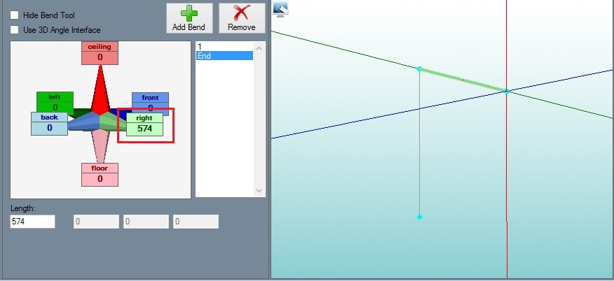
On the part model in the graphical display, the harpoon tool will be moved near the end of the part, as shown below.
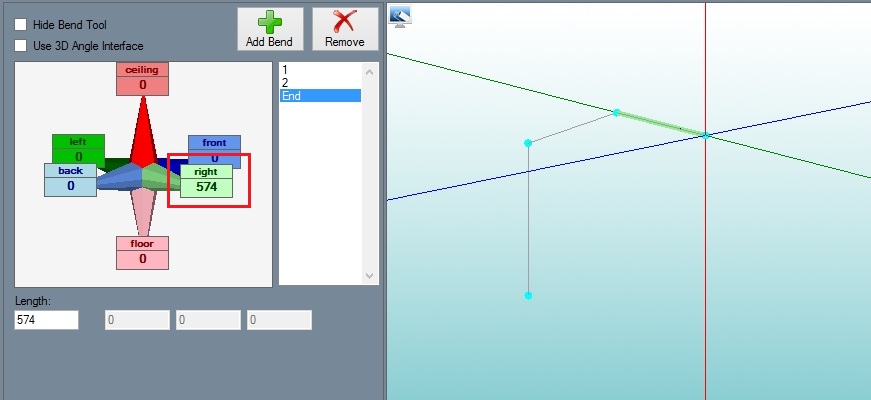
First, click light green harpoon point and type in 574 mm. Watch the part dimension, light green entry field, or the length field to get the length measurement. (Alternatives: Type the length into the entry field, click the harpoon point and directly type in the length.)
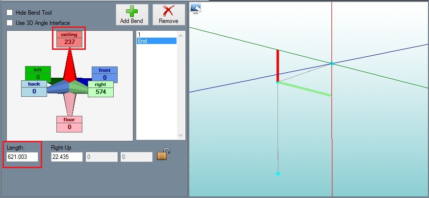
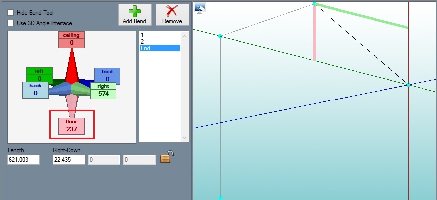
Next, the angle of the bend will be adjusted. Click the red harpoon point and enter 237 and the total length of this length is roughly 621 mm. (Alternatives: Type the value (237) into the entry field or click the harpoon point and directly type in the value.)
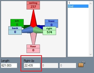
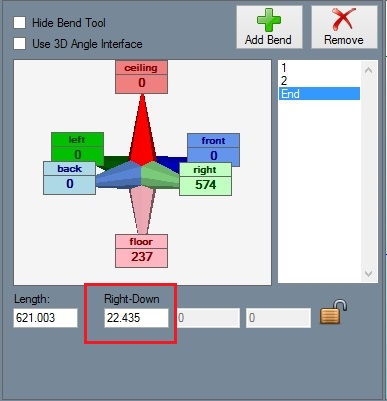
After the red harpoon point is pulled, notice that a new field will have appeared below the entry fields area, as shown below. This is the angle field. The icon next to this field will show which axis the angle is along. In this case, the value here represents the angle along the red and light green axis. The angle should be around 22.4.
Step 7
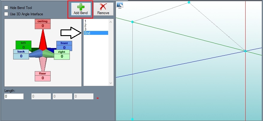
 Now, the second bend will be added to the part. Click the add bend button. Addbend.png The add bend button is located near the upper left corner, as shown in the image to the right. Once this button is clicked, a bend will be added to the part.
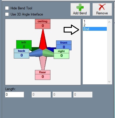
On the part model in the graphical display, the harpoon tool will be moved near the end of the part and another bend (3) will be added to the bend list, as shown below.
Click the light green harpoon point and enter 574 mm. (Alternatives: Type the value (574) into the entry field, click the harpoon point and directly type in the value.)
Now, to adjust the angle of the bend, click the pink harpoon point and enter 237 mm. (Alternatives: Type the value (237) into the entry field or click the harpoon point and directly type in the value.) This length will now measure 621 mm in the length field.
After the pink harpoon point is filled, notice that a new field will have appeared below the entry fields area, as shown below. This is the angle field. The icon next to this field will show which axis the angle is along. In this case, the value here represents the angle along the pink and light green axis. The angle should be around 22.4.
Step 8
 Next, the third bend will be added to the part. Click the add bend button.
  The add bend button is located near the upper left corner, as shown in the image to the right. Once this button is clicked, a bend will be added to the part.
On the part model in the graphical display, the harpoon tool will be moved near the end of the part and another bend (4) will be added to the bend list, as shown below.
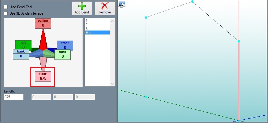
Click the pink harpoon point and enter 675 mm. (Alternatives: Type the length (675) into the entry field, click the harpoon point and directly type in the length.)
Step 9
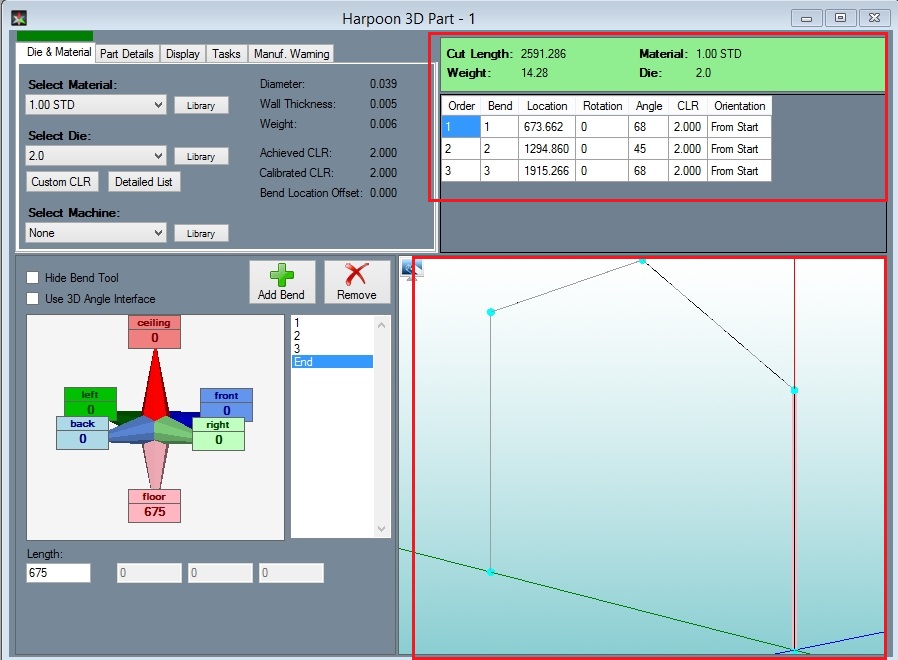
Now that each bend and length is defined, the complete 3D part model will be shown in the graphical display to the right. The part's bend information will also be generated in the results table at the top of the window. See the image below.
Depending on the options chosen in the results/output format and results/output settings tabs in the program settings menu, the results table may look slightly different.
Step 10
The part is now complete!
The part design file can be saved by going up to the main tool bar and clicking the save option. 
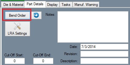
The bend order can also be adjusted in the bend order menu.
The part setup sheet can also be printed by clicking the print option on the main tool bar. 
