Difference between revisions of "Large Radius Tutorial II"
| (7 intermediate revisions by the same user not shown) | |||
| Line 1: | Line 1: | ||
| − | + | '''This is an advanced tutorial to show the capabilities of the Large Radius Module in the XYZ interface. See [[Large Radius Module]] or [[Large Radius Tutorial]] for initial and secondary information regarding the Large Radius Module.''' | |
| − | |||
| − | '''This is an advanced tutorial to show the capabilities of the Large Radius Module in the XYZ interface.''' | ||
==Things To Know== | ==Things To Know== | ||
| Line 48: | Line 46: | ||
==Creating the Part== | ==Creating the Part== | ||
| − | + | 1. Start by creating a part with '''5''' PickPoints (it will amount to '''3''' bends). Select the "'''Number of Bends'''" drop down menu and select "'''3'''" bends. | |
| − | 1. Start by creating a part with '''5''' PickPoints (it will amount to '''3''' bends). Select the "''' | ||
| − | 2. Type | + | 2. Type the information from the picture below into the corresponding value fields to create the part. |
| − | + | '''The part is now complete.''' | |
| + | [[File:Largeradius_part5.png]] | ||
| − | + | ==Enlarging the Radius== | |
| + | ===Custom CLR=== | ||
| + | 1. Once you've defined the part, select the "'''Custom CLR'''" button under the "'''Die & Material'''" tab. | ||
| − | + | 2. A window will appear prompting you to "'''Enter the new Custom CLR'''". Skip the "'''Name'''" section and type "'''8'''" into the "'''Custom CLR:'''" value field. | |
| − | + | 3. Select the "'''OK'''" [[File:OK_button1.png]] button. | |
| − | |||
| − | + | 4. Select the new CLR from the "'''Select Die'''" drop down menu. It will most likely be labeled "'''Custom 8-K50'''". | |
| − | + | '''The part in the display area will align accordingly making the 3 radii elongated.''' | |
| + | [[File:New_3_bend_part2.png]] | ||
| − | |||
| − | |||
| − | |||
| − | |||
| − | |||
| − | + | ===[[Bump Bending]]=== | |
| + | [[File:Bumpbendtool1.png|right]] "'''''If you are using a roll bender, then the Bump Bending portion of this tutorial will not be necessary for you. Bump Bending is an alternative to creating a large radius part and is geared towards the needs of users with rotary draw and rotary compression benders.'''''" | ||
| + | 1. Select the "'''Tasks'''" tab and the "'''Bump Bending'''" [[File:Bumpbending.png]] button to start the bump bending process. | ||
| − | + | 2. The Bump Bend Tool window will open and prompt you to "'''Select Die, Select Which Bend, and Number of 'Bumps''''". Choose "'''2.0'''" for a die, "'''2'''" for the bend we wish to work with, and type "'''3'''" in the number of bumps value field. | |
| − | + | 3. 3 bumps will automatically be spaced in increments along the radius of the second bend. To verify this, select the "'''Flat Layout'''" button and the part in the display area will show all the bumps that have been created. | |
| − | |||
| − | |||
| + | *'''(Note)The option to view the LRA Settings and the values of each individual bend is under the "Part Details" tab.'''" | ||
| − | + | ==Adjusting Settings== | |
| + | [[File:lr_part_settings1.png|right]] | ||
| − | + | 1. Select the "'''Part Details'''" tab and click on the "'''LRA Settings'''" button. | |
| − | |||
| − | + | *The "'''Part Settings'''" window will open. | |
| − | |||
| − | + | 2. Select the "'''Output Results'''" tab and select the "'''Bend Angle'''" drop down menu within the far right "'''Tolerance'''" section. | |
| − | |||
| + | 3. Select the option with the decimal in the hundredths place: "'''n.nn'''". This will give you a much more accurate reading of the bend angles located in the white values box above the display area. | ||
| − | |||
| − | |||
| − | |||
| − | |||
| − | |||
| − | |||
| Line 129: | Line 118: | ||
===Flat Layout=== | ===Flat Layout=== | ||
"'''''If you are using a roll bender, then the Flat Layout portion of this tutorial will not be necessary for you. Flat Layout shows details before creating a large radius part and is geared towards the needs of users with rotary draw and rotary compression benders.'''''" | "'''''If you are using a roll bender, then the Flat Layout portion of this tutorial will not be necessary for you. Flat Layout shows details before creating a large radius part and is geared towards the needs of users with rotary draw and rotary compression benders.'''''" | ||
| + | |||
1. Select the "'''Tasks'''" tab and click on the "'''Flat Layout'''" button. | 1. Select the "'''Tasks'''" tab and click on the "'''Flat Layout'''" button. | ||
| + | |||
*In the Flat Layout window, users can see all dimensions of the part including the start, center and end of each bend, as well as rotations, angles, spring angles and the CLR. | *In the Flat Layout window, users can see all dimensions of the part including the start, center and end of each bend, as well as rotations, angles, spring angles and the CLR. | ||
| + | |||
2. Here, you have the option to "'''Print'''" out these details. | 2. Here, you have the option to "'''Print'''" out these details. | ||
| + | |||
"'''The tutorial is now complete.'''" | "'''The tutorial is now complete.'''" | ||
Latest revision as of 06:25, 3 October 2014
This is an advanced tutorial to show the capabilities of the Large Radius Module in the XYZ interface. See Large Radius Module or Large Radius Tutorial for initial and secondary information regarding the Large Radius Module.
Contents
Things To Know
"If you are using a roll bender, then the Bump Bending portion of this tutorial will not be necessary for you. Bump Bending is an alternative to creating a large radius part and is geared towards the needs of users with rotary draw and rotary compression benders."
- This tutorial is designed to walk the user through creating an XYZ design and creating a large radius part. As you go through this tutorial, later procedures will assume that you understand all earlier procedures. Because of this, it is very important that you carefully step through this guide, understanding everything along the way and following all steps in order.
- A few key items need to be addressed before starting the step-by-step instructions of this tutorial. It is very important for Bend-Tech users to completely understand these items:
- 1) PickPoints
- PICKPOINTS ARE USED FOR EVERYTHING. The XYZ part of the software is largely run in full 3D. Because a computer screen is only 2D, there is an unlimited amount of depth behind and in front of the cursor. A PickPoint is a point in 3D space that can be used for creating, editing, and placing parts in Header design. PickPoints can be placed in a 2D environment by having their depth manually entered in the appropriate value fields.
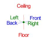
- There are 2 types of PickPoints; Those automatically created by the part by default (various colors) and user-defined points (green). In addition, the initial (0,0,0) point is an automatic point that resides at the center of the Tri-Star. The Tri-Star is our directional definition locator.
- 2) Center Line & Apex
-
- Center Line: In the Assembly interface environment we are working exclusively with the center-line of a part, as compared to the inside or outside.
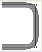
- Apex: Most bend locations are created in the Assembly interface with the Apex. Our definition of apex is the intersection of the straight tubes as if there wasn’t a radius.
- This is demonstrated in the picture below.
- 3) Locational Orientation
-
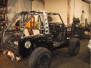
- Designing seems to work the best if users imagine they are standing behind the vehicle at a 45 degree angle. This way left is left and right is right. Take a minute and examine the Tri-Star to get your orientation.
- Notice how the truck in the picture is setup with the same orientation.
- 4) Defining Parts
-
- It is possible to create parts in the template and custom part interfaces, however, starting out this way tends to get confusing for new users of the software. It appears that there is a higher level of success with customers who start out designing parts directly in the Assembly interface. However, see Large Radius Tutorial for that. This is the advanced version.
Start Up
1. Start by double clicking the "Bend-Tech 7x" icon to start up the program.2. Select the "XYZ" icon ![]() in the Task Menu under the "Create New" section to open the XYZ interface. The window that opens should be labeled [XYZ Part - 1].
in the Task Menu under the "Create New" section to open the XYZ interface. The window that opens should be labeled [XYZ Part - 1].
3. For the purposes of this tutorial, click the "Maximize" button ![]() at the top right of the railing design window.
at the top right of the railing design window.
4. Also, for the purposes of this tutorial, zoom out significantly by spinning the wheel on your mouse so that the Tri-Star is about the size of a pea in the lower left corner of the display area.
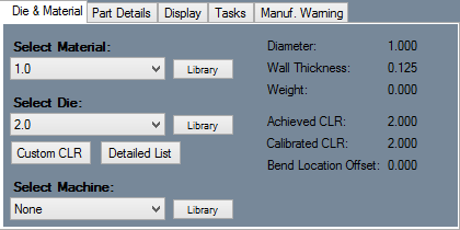
5. The "Die & Material" tab is located in the upper left corner of the window. Select the "1.00 Material" and "2.0 Die" as seen here. (Selecting a very large die will limit the amount of Bump Bends when dealing with a limited amount of tubing and will not give your part the desired effect.)
Creating the Part
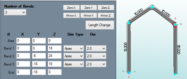
1. Start by creating a part with 5 PickPoints (it will amount to 3 bends). Select the "Number of Bends" drop down menu and select "3" bends.
2. Type the information from the picture below into the corresponding value fields to create the part.
Enlarging the Radius
Custom CLR
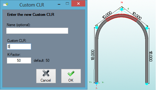
1. Once you've defined the part, select the "Custom CLR" button under the "Die & Material" tab.
2. A window will appear prompting you to "Enter the new Custom CLR". Skip the "Name" section and type "8" into the "Custom CLR:" value field.
4. Select the new CLR from the "Select Die" drop down menu. It will most likely be labeled "Custom 8-K50".
The part in the display area will align accordingly making the 3 radii elongated.
Bump Bending
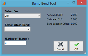
"If you are using a roll bender, then the Bump Bending portion of this tutorial will not be necessary for you. Bump Bending is an alternative to creating a large radius part and is geared towards the needs of users with rotary draw and rotary compression benders."1. Select the "Tasks" tab and the "Bump Bending" ![]() button to start the bump bending process.
button to start the bump bending process.
2. The Bump Bend Tool window will open and prompt you to "Select Die, Select Which Bend, and Number of 'Bumps'". Choose "2.0" for a die, "2" for the bend we wish to work with, and type "3" in the number of bumps value field.
3. 3 bumps will automatically be spaced in increments along the radius of the second bend. To verify this, select the "Flat Layout" button and the part in the display area will show all the bumps that have been created.
- (Note)The option to view the LRA Settings and the values of each individual bend is under the "Part Details" tab."
Adjusting Settings
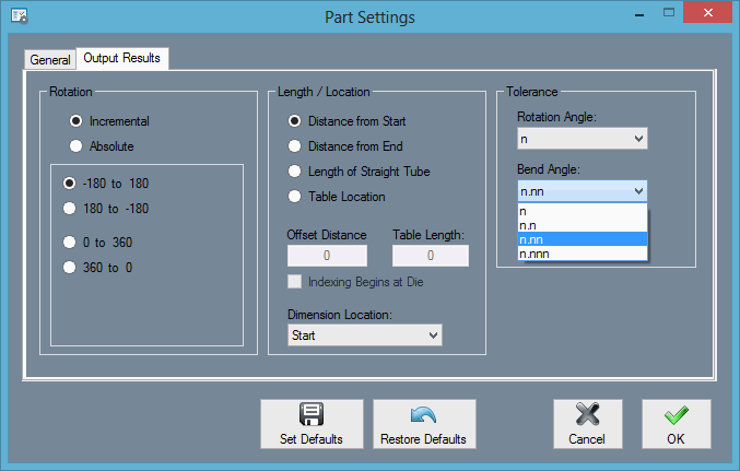
1. Select the "Part Details" tab and click on the "LRA Settings" button.
- The "Part Settings" window will open.
2. Select the "Output Results" tab and select the "Bend Angle" drop down menu within the far right "Tolerance" section.
3. Select the option with the decimal in the hundredths place: "n.nn". This will give you a much more accurate reading of the bend angles located in the white values box above the display area.
Flat Layout
"If you are using a roll bender, then the Flat Layout portion of this tutorial will not be necessary for you. Flat Layout shows details before creating a large radius part and is geared towards the needs of users with rotary draw and rotary compression benders."
1. Select the "Tasks" tab and click on the "Flat Layout" button.
- In the Flat Layout window, users can see all dimensions of the part including the start, center and end of each bend, as well as rotations, angles, spring angles and the CLR.
2. Here, you have the option to "Print" out these details.
"The tutorial is now complete."
