Difference between revisions of "Tekla Import Guide"
(→Define) |
(→Define Section) |
||
| Line 35: | Line 35: | ||
==Define== | ==Define== | ||
===Define Section=== | ===Define Section=== | ||
| − | 1. '''Create Tube By Dragging:''' Click the '''Create Tube By Dragging''' [[File:Create_Tube_By_Dragging_Tekla1.png]] button, then click and drag your cursor | + | 1. '''Create Tube By Dragging:''' Click the '''Create Tube By Dragging''' [[File:Create_Tube_By_Dragging_Tekla1.png]] button, then click and drag your cursor of your mouse over any straight section of tubing that you'd like to define. '''IMPORTANT:''' ''This works best if you refrain from including bends, zoom in close to your intended tube, and drag the line in a direction that runs opposite of the length of tubing you are trying to define.'' |
Revision as of 09:08, 10 May 2016
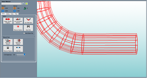
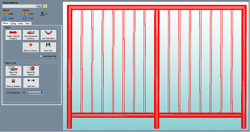
Bend-Tech's Tekla importer is useful for customers with .step and .iges file types that contain a boundary representation of the tube model. These file types are exported from the Tekla software programs. Examples are illustrated in the pictures below.
Contents
Tekla Import Access
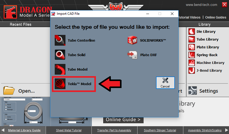
- To access the Tekla Model Importer, select the CAD Import Menu
 from the Task Menu and select the Tekla Model
  option from the list.
Open a Project
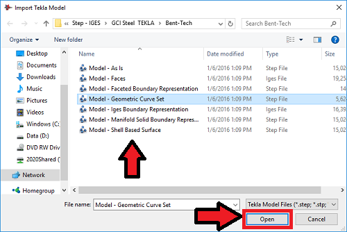
- Select a file from the list and click the Open button to open it in the Tekla Import screen.
Material Definition
1. The Select Material: drop down menu will be grayed out until the user has fully tracked the imported part. Once the part is tracked, it will need to be assigned a material which matches its Defined: outer diameter and wall thickness.
2. If a material is not set up in your material library that will match the imported part, clicking the Plus: ![]() button will add the imported material for you and assign it to the current part or project.
button will add the imported material for you and assign it to the current part or project.
3. The Material: section will show which material is chosen from the Select Material: drop down menu above. The Outside Diameter (OD) of the material will be shown next to the orange icon and the Material Wall Thickness will be shown next to the blue icon.
4. The Defined: section will show which material is applied to the part after importing. The detected Outside Diameter (OD) of the material will be shown next to the orange icon and the detected Material Wall Thickness will be shown next to the blue icon.
5. The number of bends detected in the part will be shown next to this icon.
Define
Define Section
1. Create Tube By Dragging: Click the Create Tube By Dragging  button, then click and drag your cursor of your mouse over any straight section of tubing that you'd like to define. IMPORTANT: This works best if you refrain from including bends, zoom in close to your intended tube, and drag the line in a direction that runs opposite of the length of tubing you are trying to define.


