Tekla Import Guide
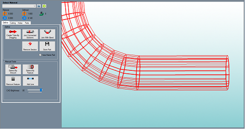
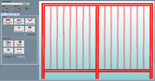
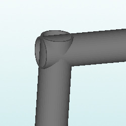
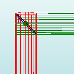
Bend-Tech's Tekla importer is useful for customers with .step and .iges file types that contain a boundary representation of the tube model. These file types are exported from the Tekla software programs. Examples are illustrated in the pictures below.
Contents
Tekla Import Access
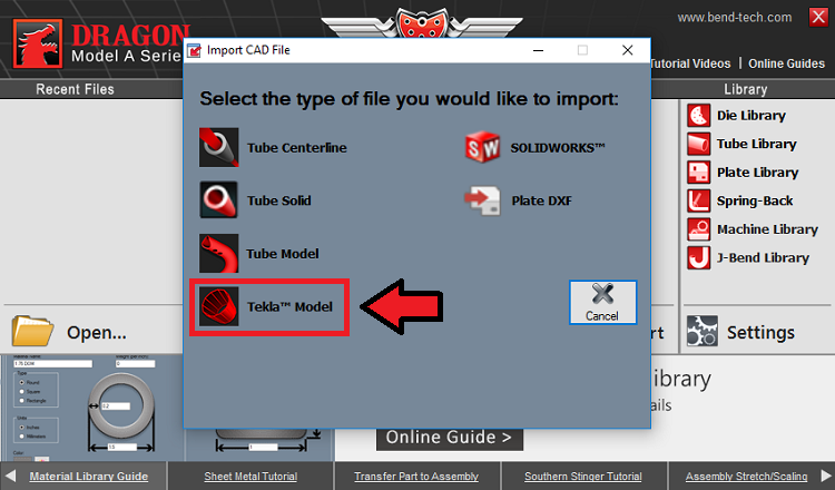
- To access the Tekla Model Importer, select the CAD Import Menu
 from the Task Menu and select the Tekla Model
  option from the list.
Open a Project
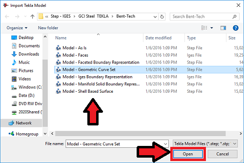
- Select a file from the list and click the Open button to open it in the Tekla Import screen.
Material Definition
1. The Select Material: drop down menu will be grayed out until the user has fully tracked the imported part. Once the part is tracked, it will need to be assigned a material which matches its Defined: outer diameter and wall thickness.
2. If a material is not set up in your material library that will match the imported part, clicking the Plus: ![]() button will add the imported material for you and assign it to the current part or project.
button will add the imported material for you and assign it to the current part or project.
3. The Material: section will show which material is chosen from the Select Material: drop down menu above. The Outside Diameter (OD) of the material will be shown next to the orange icon and the Material Wall Thickness will be shown next to the blue icon.
4. The Defined: section will show which material is applied to the part after importing. The detected Outside Diameter (OD) of the material will be shown next to the orange icon and the detected Material Wall Thickness will be shown next to the blue icon.
5. The number of bends detected in the part will be shown next to this icon.
Define
Define Section
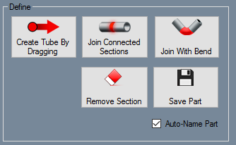
- In the Define section of the Tekla Import screen, users will be able to use the following basic functions in order to define their part in preparation for use in the Bend-Tech software. After each part is fully defined, it can then be saved to the Parts tab before it can be transferred to one of our other designers.
Create Tube By Dragging:
Click the Create Tube By Dragging  button, then click and drag your cursor of your mouse over any straight section of tubing that you'd like to define. IMPORTANT: This works best if you refrain from including bends, zoom in close to your intended tube, and drag the line in a direction that runs opposite of the length of tubing you are trying to define. See the illustration below for more detail.
Join Connected Sections:
Click the Join Connected Sections  button, then select a straight length of defined tubing followed by an adjoining straight length of defined tubing. You will always have to click the center line of the defined straight in order to select it. The tube will highlight red to indicate that it is ready to be selected. See the illustration below for more detail.
Join With Bend:
Click the Join With Bend  button, then select a straight length of defined tubing followed by an adjoining straight length of defined tubing that is separated by a bend. You will always have to click the center line of the defined straight in order to select it. The tube will highlight red to indicate that it is ready to be selected. See the illustration below for more detail.
Remove Section:
Click the Remove Section  button, then a straight or bent section of defined tubing in order to take away the definition for that section. You will always have to click the center line of the defined straight in order to select it. The tube will highlight red to indicate that it is ready to be selected. See the illustration below for more detail.
Save Part:
Before saving a part, click on the green Plus: ![]() button next to the Select Material drop down menu and the detected material will be added to the part for you. Then, click the Save Part
button next to the Select Material drop down menu and the detected material will be added to the part for you. Then, click the Save Part  button when a single part has been fully defined and it will be saved to the Parts tab and it will be ready to transfer to another designer.
Auto-Name Part
When the Auto-Name Part ![]() check box is checked, the part will be named automatically during the saving process. If it is unchecked, a window will appear prompting you to name the part when you click the Save Part button.
check box is checked, the part will be named automatically during the saving process. If it is unchecked, a window will appear prompting you to name the part when you click the Save Part button.
Manual Tools Section
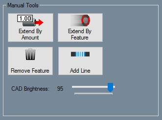
- In the Manual Tools section in the Tekla Import screen, users can manually add or subtract from a defined part or from the basic geometry of the imported file itself using the tools available.
Extend By Amount:
Click the Extend By Amount  button followed by a defined straight length of tubing in order to extend that length of tubing by a designated value. A window will appear asking for the value that the tube end will be extended by, so enter the value for the extension and click the OK button to apply the change.
Extend By Feature:
Click the Extend By Feature  button followed by a defined straight length of tubing in order to extend that length of tubing by clicking on a feature that represents the new length.
Remove Feature:
Click the Remove Feature  button followed by a geometric feature in the design to remove it. This may help, in some cases, to help in defining a certain part in the design. Unnecessary geometric features can interfere with the defining process.
Add Line:
Click the Add Line  button followed by a location in the design that represents the start of the new line, then a location that represents the end of the new line. Creating new lines of geometry in the imported project may help bridge any gaps between parts to help them define properly.
CAD Brightness:
Adjusting the CAD Brightness ![]() will either brighten or dim the color of all geometric features within the imported design. This can be used to see defined parts when dimmed and see raw geometric features when brightened.
will either brighten or dim the color of all geometric features within the imported design. This can be used to see defined parts when dimmed and see raw geometric features when brightened.
Cutting
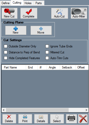
The Cutting tab contains the tools necessary for adding cuts to the ends of parts. Wrappers can be printed which, when wrapped around the end of a tube, mark where the tube needs to be cut.
Make Cuts
Click the New Cut ![]() button and click a part. The cut part will be highlighted in green once selected. Click a second part, plane, or multiple parts that the first part will be cut to fit against. The second and any consecutive selected parts will be highlighted in red. Click the Complete
button and click a part. The cut part will be highlighted in green once selected. Click a second part, plane, or multiple parts that the first part will be cut to fit against. The second and any consecutive selected parts will be highlighted in red. Click the Complete ![]() button. The cut should appear in the list of cuts in the Cutting tab and shown on the assembly.
button. The cut should appear in the list of cuts in the Cutting tab and shown on the assembly.
Click the "Auto-Cut" ![]() button to let the software attempt to generate all cuts in the assembly project.
button to let the software attempt to generate all cuts in the assembly project.
Click the "Auto-Miter" ![]() button to extend the lengths of intersecting tubes past their center line so they can be cut equally.
button to extend the lengths of intersecting tubes past their center line so they can be cut equally.
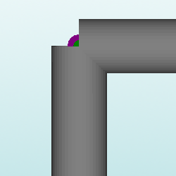
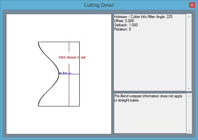
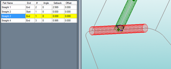
When viewing the details for the wrappers for a mitered cut, they should have these qualities.
Cutting Plane
Using the "Cutting Plane" function to cut a section of tube is different from cutting tubes that intersect. This tool is used for cutting a specific place on a bend or straight tube that does not intersect another tube.
Using the cutting plane feature, a custom plane can be defined and used to place cuts anywhere on the assembly design.
To place a cutting plane, click the "New" ![]() button under the "Cutting" tab and click on a PickPoint to define the center/base point of the plane. Then click the first and second direction of the plane.
button under the "Cutting" tab and click on a PickPoint to define the center/base point of the plane. Then click the first and second direction of the plane.
Once a plane is place in the assembly, it can be used as a cutting feature and will allow straight cuts to be placed anywhere.
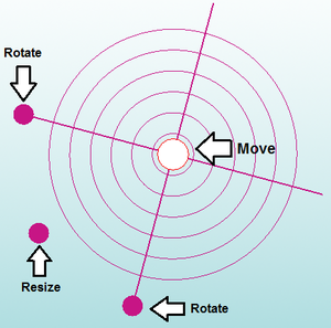
To move the plane, click the "Move" ![]() button. Then click and drag the move tools directly on the plane to move, resize, and rotate the plane. See image below.
button. Then click and drag the move tools directly on the plane to move, resize, and rotate the plane. See image below.
Once the cutting plane in in the correct position, the user can record a cut by selecting the "New Cut" ![]() button.
button.
Then, select the tube that you are trying to cut, followed by the cutting plane itself. If you've done everything right, the cutting plane will be highlighted when you place your cursor over it.
Lastly, select the "Complete" ![]() button and the new cut and information will show up on the left of the screen in the Cut Chart section.
button and the new cut and information will show up on the left of the screen in the Cut Chart section.
Cut Settings
If the Outside Diameter Only option is checked, the software will not display the inside diameter cut line for each cut. Using a hole saw requires the checking of the outside of the material only. "Check" the option "Outside Diameter Only".
Using a grinder or plasma cutter requires checking of both sides of the material. "UnCheck" the option "Outside Diameter Only".
If Distance to Perp of Bend is checked, The red line will indicate the distance to the perpendicular of the bend. The cut wrapper's red line will display the distance to the tangent of the nearest bend combined with the outside radius of the bend.
If the Hide Completed Features option is checked, completed features from the cut will be hidden in the design.
If the Ignore Tube Ends option is checked, all cuts will ignore the excess tubing leftover from all other cuts.
If Mitered Cut is checked, all cuts will be calculated as straight mitered cuts. If you are using a hole saw to cut your tubes leave Mitered Cut unchecked.
Cut Chart
A chart displaying a list of all the cuts currently applied to the assembly will be shown as well.
Click on a cut to see a preview of the cut on the 3D model of the assembly.
Click Delete ![]() to remove the cut from the tube, or click Delete All
to remove the cut from the tube, or click Delete All ![]() to remove all cuts from the Assembly project.
to remove all cuts from the Assembly project.
Click Print ![]() to print the currently selected wrapper, or click Print All
to print the currently selected wrapper, or click Print All ![]() to print out all wrappers for the entire Assembly project.
to print out all wrappers for the entire Assembly project.
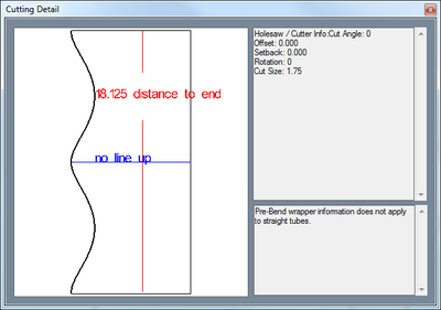
Click the Details button ![]() to see a preview of the cutting wrapper. On each wrapper, there is a red line with a number on it. This line is used for lining up a wrapper on a tube. The number is the distance from the end of the tube that the red line should be.
to see a preview of the cutting wrapper. On each wrapper, there is a red line with a number on it. This line is used for lining up a wrapper on a tube. The number is the distance from the end of the tube that the red line should be.
Click the Select button ![]() and click on a cut in the display area to select it from the assembly directly.
and click on a cut in the display area to select it from the assembly directly.
Cutting Definitions
- Setback - Distance from the end of the tube to the centerline of the cross tube. This point is the intersection of the cross tube (centerline) and the centerline of the cut tube.
- Offset - The up/down distance from the centerline of the cut tube to the centerline of the cross tube when looking at the face of the cut.
- Angle - The plunge angle of the holesaw. A zero degree angle would be a plunge at a perpendicular (90 degree) angle to the cut tube.
- Rotation - The rotation of the holesaw plunge in relation to the closest bend (or opposite side of the tube in the case of a straight tube).
Holes
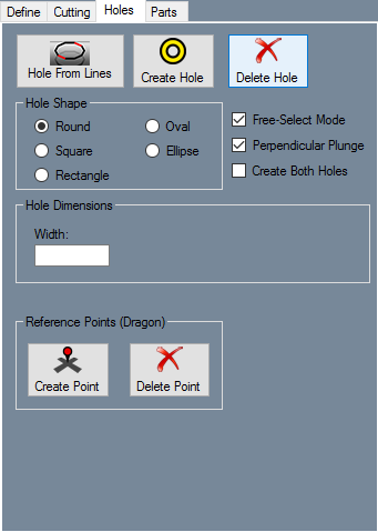
- The Holes tab is used to create hole geometry on your defined parts in order to transfer the data to the Dragon designer. These holes can then be assigned an action of cutting, engraving or marking based on your needs.
Hole From Lines:
Click on the Hole From Lines ![]() button followed by the defined part you'd like to place the hole on, then select a geometric feature that represents the first line of the hole followed finally by a line on the opposite side of the intended hole cutout.
button followed by the defined part you'd like to place the hole on, then select a geometric feature that represents the first line of the hole followed finally by a line on the opposite side of the intended hole cutout.
Create Hole:
Click on the Create Hole ![]() button followed by the defined part you'd like to place the hole on, then, if Free Select is enabled, click anywhere on the outer edge of the tubing in order to place the hole there. Without the use of Free Select, you must have a point placed in order to designate the hole's center point. For holes requiring a direction or angle (Square, Rectangle, Oval, Ellipse) after the hole's center point has been established, you will also be prompted to select a new point or line to indicate this.
button followed by the defined part you'd like to place the hole on, then, if Free Select is enabled, click anywhere on the outer edge of the tubing in order to place the hole there. Without the use of Free Select, you must have a point placed in order to designate the hole's center point. For holes requiring a direction or angle (Square, Rectangle, Oval, Ellipse) after the hole's center point has been established, you will also be prompted to select a new point or line to indicate this.
Delete Hole:
Click on the Delete Hole ![]() button followed by a hole you'd like to remove, then the hole's geometry will be deleted from the design.
button followed by a hole you'd like to remove, then the hole's geometry will be deleted from the design.
Hole Shape:
- The Hole Shape section is where you will designate the type/shape of the hole that will be inserted into the design.
Round: Select the Round ![]() option to create a round hole in the design. The size of this hole will be determined by the value you enter into the Width: value field in the Hole Dimensions section.
option to create a round hole in the design. The size of this hole will be determined by the value you enter into the Width: value field in the Hole Dimensions section.
Square: Select the Square ![]() option to create a square hole in the design. The size of this hole will be determined by the values you enter into the Width: and Corner Radius: value fields in the Hole Dimensions section.
option to create a square hole in the design. The size of this hole will be determined by the values you enter into the Width: and Corner Radius: value fields in the Hole Dimensions section.
Rectangle: Select the Rectangle ![]() option to create a rectangular hole in the design. The size of this hole will be determined by the values you enter into the Width:, Height: and Corner Radius: value fields in the Hole Dimensions section.
option to create a rectangular hole in the design. The size of this hole will be determined by the values you enter into the Width:, Height: and Corner Radius: value fields in the Hole Dimensions section.
Oval: Select the Oval ![]() option to create a oval hole in the design. The size of this hole will be determined by the values you enter into the Width: and Height: value fields in the Hole Dimensions section.
option to create a oval hole in the design. The size of this hole will be determined by the values you enter into the Width: and Height: value fields in the Hole Dimensions section.
Ellipse: Select the Ellipse ![]() option to create a ellipse hole in the design. The size of this hole will be determined by the values you enter into the Width: and Height: value fields in the Hole Dimensions section.
option to create a ellipse hole in the design. The size of this hole will be determined by the values you enter into the Width: and Height: value fields in the Hole Dimensions section.
Misc Check Box Options:
- These miscellaneous options are where you can set physical attributes to the hole(s) your are placing in the design and choose whether or not the holes placed are tied to a point or placed freely.
Free-Select Mode: Check the Free-Select Mode ![]() check box and you will be able to place your hole exactly where you click your cursor.
check box and you will be able to place your hole exactly where you click your cursor.
Perpendicular Plunge: Check the Perpendicular Plunge ![]() check box and you will be able to place your hole at a 90 degree perpendicular orientation to the tubing. If this box is unchecked, you will have the option to click a point after the hole has been placed to indicate the angle and direction of the plunge.
check box and you will be able to place your hole at a 90 degree perpendicular orientation to the tubing. If this box is unchecked, you will have the option to click a point after the hole has been placed to indicate the angle and direction of the plunge.
Create Both Holes: Check the Create Both Holes ![]() check box and holes will be placed on both sides of the tubing when a hole is placed.
check box and holes will be placed on both sides of the tubing when a hole is placed.
Hole Dimensions:
- The Hole Dimensions section is where you will enter the dimension values for the hole you have selected before you place it in the design.
Parts
- The part names will be listed here along with their respective material and die information.
Select All
- This will select all of the parts in the parts list. They can then all be transferred to an Assembly if directed by the user.
Select None
- This will deselect all of the parts in the parts list.
Delete Part
- This will delete the selected part(s) from the parts list and will remove their definition in the display screen to the right.
