Difference between revisions of "Dragon Die Calibration"
| (9 intermediate revisions by the same user not shown) | |||
| Line 9: | Line 9: | ||
'''...OR''' | '''...OR''' | ||
| − | '''2.)''' Select the '''Die Library''' option from the [[View#Task Menu|Task Menu]] that appears when the software starts up, when all designs are closed, or through the view menu. | + | '''2.)''' Select the '''Die Library''' option from the '''[[View#Task Menu|Task Menu]]''' that appears when the software starts up, when all designs are closed, or through the view menu. |
<h3>Die Details</h3> | <h3>Die Details</h3> | ||
| Line 25: | Line 25: | ||
[[File:Dragon_C1.png]] | [[File:Dragon_C1.png]] | ||
| + | <h4>Action Buttons</h4> | ||
| + | |||
| + | '''To manually add a die to the library''', click the '''Add New''' button. [[File:add_die.png]] After this button is clicked, all the attribute fields will be available to enter data into. Once all the required details are provided, click the '''Save''' button [[File:save_die.png]] to add the die to the library. | ||
| + | |||
| + | '''To delete a die from the library''', click on the die you'd like to delete from the die list and select the '''Delete''' [[File:Die_Delete1.png]] button. | ||
| + | |||
| + | '''To clone a previously created die/make a copy''', click on the die you'd like to clone from the die list and select the '''Clone''' [[File:Die_Attack_Of_The_Clones1.png]] button. | ||
| + | |||
| + | '''Close the window''' with the '''Close''' [[File:Close1.png]] button. | ||
<h3>Calibration Values</h3> | <h3>Calibration Values</h3> | ||
| Line 65: | Line 74: | ||
[[File:Dragon_C4.png]] | [[File:Dragon_C4.png]] | ||
| + | |||
| + | <h2>Bend Marks</h2> | ||
[[File:Bend_Marks1.png|right]] | [[File:Bend_Marks1.png|right]] | ||
| − | |||
| − | |||
<h3>Die List</h3> | <h3>Die List</h3> | ||
| Line 74: | Line 83: | ||
<h3>Bend Marking</h3> | <h3>Bend Marking</h3> | ||
This section is where users will set up the manner in which their bend markings will appear on a part before it is sent out as a flat layout .dxf file or sent to the Dragon machine. | This section is where users will set up the manner in which their bend markings will appear on a part before it is sent out as a flat layout .dxf file or sent to the Dragon machine. | ||
| − | |||
| − | |||
| − | |||
| − | |||
| − | |||
| − | |||
===Bend Mark Format:=== | ===Bend Mark Format:=== | ||
| Line 98: | Line 101: | ||
===Bend Line Length:=== | ===Bend Line Length:=== | ||
Here, enter the bend line (vertical line representing the bend location) length and the bend line will adjust accordingly. | Here, enter the bend line (vertical line representing the bend location) length and the bend line will adjust accordingly. | ||
| + | |||
| + | ===Rotation Line Length:=== | ||
| + | Here, enter the rotation line (horizontal line representing the rotation) length and the rotation line will adjust accordingly. | ||
===Rotation Offset Angle:=== | ===Rotation Offset Angle:=== | ||
| − | Here, enter the rotation offset amount for the rotation alignment marks. This offset is calculated from the inside of the bend. | + | Here, enter the rotation offset amount for the rotation alignment marks. This offset is calculated from the inside of the bend and can be determined by following the instructions in the '''Rotation Wizard'''. |
| + | |||
| + | ===[[Dragon Rotation Calibration|Rotation Wizard]]=== | ||
===Text Font:=== | ===Text Font:=== | ||
Here, choose the font of the text you would like to show up on your design. | Here, choose the font of the text you would like to show up on your design. | ||
| + | |||
| + | ===Text Location:=== | ||
| + | Here, choose the location of the text in reference to the front or back of the bend mark. | ||
===Text Size:=== | ===Text Size:=== | ||
Here, enter the text size as it will show up on your design. | Here, enter the text size as it will show up on your design. | ||
| + | |||
| + | ===Text Offset Rotation:=== | ||
| + | Here, enter the rotational offset amount for the bend mark text. This will offset the text along the y-axis. | ||
===Text Location Offset:=== | ===Text Location Offset:=== | ||
Here, enter the offset amount for the bend mark text. The bend mark text will be located (along with the tube length) this distance away from the bend mark. | Here, enter the offset amount for the bend mark text. The bend mark text will be located (along with the tube length) this distance away from the bend mark. | ||
| − | |||
| − | |||
| − | |||
| − | |||
| − | |||
| − | |||
| − | |||
| − | |||
| − | |||
===Text Angle:=== | ===Text Angle:=== | ||
Here, enter the angle that will be applied to the text. | Here, enter the angle that will be applied to the text. | ||
| − | |||
| − | |||
| − | |||
| − | |||
| − | |||
| − | |||
| − | |||
Latest revision as of 13:49, 14 December 2016
Contents
- 1 Die Calibration
- 2 Die Details
- 3 Calibration Values
- 4 Calibration Wizard
- 5 Calibration Worksheet
- 6 OEM Die List
- 7 Bend Marks
- 7.1 Die List
- 7.2 Bend Marking
- 7.3 Bend Mark Format:
- 7.4 Include Bend Number
- 7.5 Include Bend Angle
- 7.6 Include Degree Symbol
- 7.7 Material OD (Preview Only):
- 7.8 Bend Line Length:
- 7.9 Rotation Line Length:
- 7.10 Rotation Offset Angle:
- 7.11 Rotation Wizard
- 7.12 Text Font:
- 7.13 Text Location:
- 7.14 Text Size:
- 7.15 Text Offset Rotation:
- 7.16 Text Location Offset:
- 7.17 Text Angle:
Die Calibration
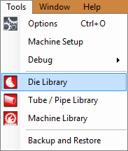
To open the Die Library where the Calibration tools are located:
1.) Go to the Tools menu, select Die Library.
...OR
2.) Select the Die Library option from the Task Menu that appears when the software starts up, when all designs are closed, or through the view menu.
Die Details
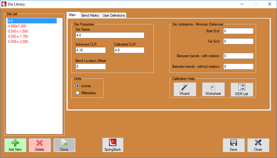
Die Name: The die name is the name that will be assigned to the die. This name will be used to refer to this specific die everywhere in the software.
Achieved CLR: The achieved CLR is the centerline radius of the die that compensates for any spring back. This value is usually slightly larger than the die size CLR.
Calibrated CLR: The Calibrated CLR is the used in the software to determine the amount of stretch or growth in the bending process for that material and die.
Bend Location Offset: The Bend Location Offset (BLO) is the distance added to the bend locations to offset the difference between the line-up mark on the die or bender to the true start of bend.
Units: The unit type selection lets you specify whether the values you entered for the die are in inch units or millimeters. This option is only available in Bend-Tech SE.
Action Buttons
To manually add a die to the library, click the Add New button. ![]() After this button is clicked, all the attribute fields will be available to enter data into. Once all the required details are provided, click the Save button
After this button is clicked, all the attribute fields will be available to enter data into. Once all the required details are provided, click the Save button ![]() to add the die to the library.
to add the die to the library.
To delete a die from the library, click on the die you'd like to delete from the die list and select the Delete ![]() button.
button.
To clone a previously created die/make a copy, click on the die you'd like to clone from the die list and select the Clone ![]() button.
button.
Close the window with the Close ![]() button.
button.
Calibration Values
The best way to calibrate a new die when adding it to the die library is to use the Die Calibration Wizard. If you are already familiar with calibration process, you can use the quicker, simpler Die Worksheet. These can be found in the die library under the Help section.
Both the Calibration Worksheet and the Calibration Wizard will walk you through bending a simple test piece and measuring the results. These result will let the software calculate your calibration values you need for the dies in the software.
Calibration Wizard
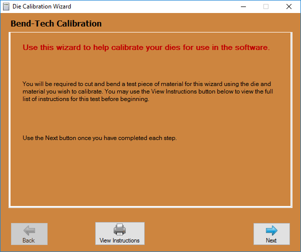
The Calibration Wizard will walk you through bending and measuring a test piece of material using the die you are trying to calibrate. The wizard is a step-by-step process and is recommended for those who are new to the software and/or calibrating dies.
Follow the on-screen instructions when using the wizard. It is recommended to select the View Instructions button in order to print out the full instructions. This way you will not need to return to the computer multiple times during the test process. The printed sheet will also provide you with the space to write your test results. The first step is to pick your bender from the drop-down menu at the top of the window. If you cannot find your bender (or a bender similar to yours), just select the Any Rotary Draw, Any Rotary Compression or Any Center Compression option from this list.
Once a bender option has been chosen, follow the instructions very carefully. Remember to accurately measure and write down the cut length BEFORE bending the test piece! Use the Back and Next buttons to navigate through the instructions. After all these values have been entered, the achieved CLR, calibrated CLR, and bend location offset values will be generated. Click the Add Die button to add these values to current die in the die library.
Calibration Worksheet
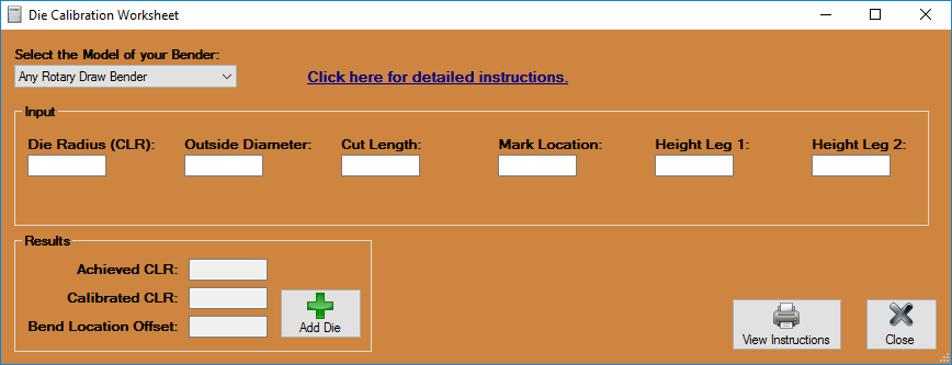
If you are familiar with the test process and simply need the software to calculate the results, you can use the simpler Calibration Worksheet.
Simply fill in the required fields and the software will calculate the results. Once you are happy with the results, you can select the Add Die button to add the results to your die library.
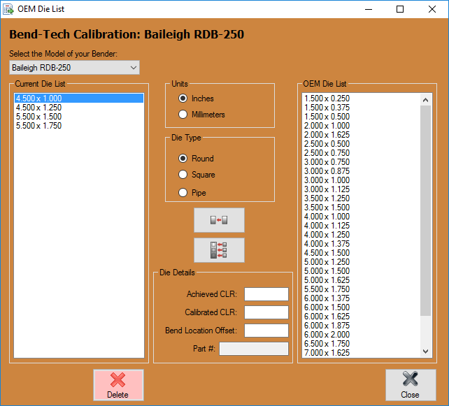
OEM Die List
If you simply wish to start designing your parts and are not concerned with obtaining accurate bending results, you may choose to use the OEM Die List. This list contains the standard dies for some of the most common benders. The calibration values for these dies are a close estimate and can be used for designing parts in the software. However, it is strongly recommended to perform an actual calibration test (using the wizard or worksheet mentioned above) before using these dies to bend any parts.
If you find yourself having any trouble with a die from the OEM List, you will need to perform a calibration test yourself.
Bend Marks
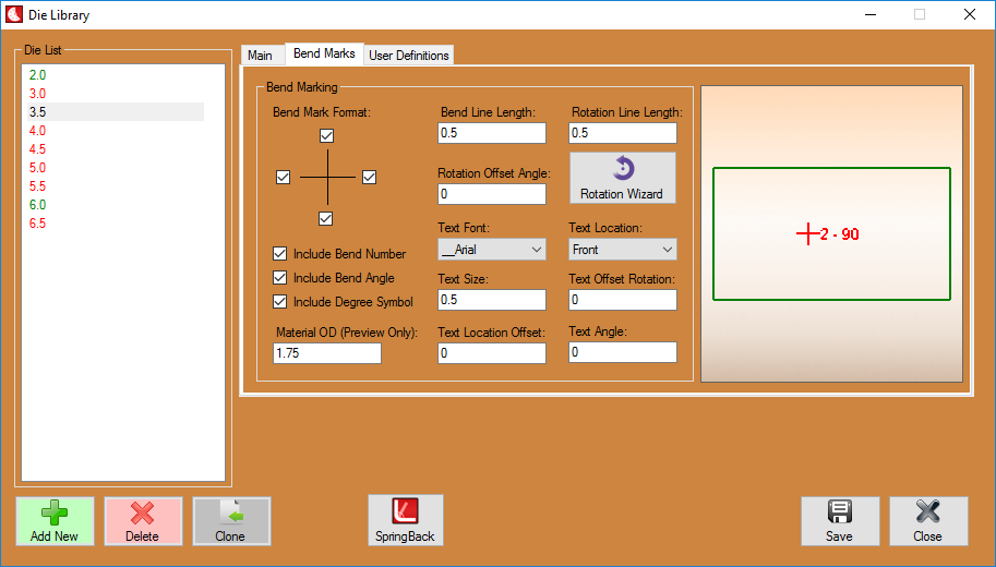
Die List
Select a die from the Die List and your bend marking information for that die will be displayed in the Bend Marking section to the right. If there are no dies in the list to the left, you must create them first in the Die Library.
Bend Marking
This section is where users will set up the manner in which their bend markings will appear on a part before it is sent out as a flat layout .dxf file or sent to the Dragon machine.
Bend Mark Format:
Here, check the checkboxes indicating which of the four bend mark lines you would like to be shown on the design applicable to the selected die.
Include Bend Number
Here, check the Include Bend Number checkbox to include the bend number in the design applicable to the selected die.
Include Bend Angle
Here, check the Include Bend Angle checkbox to include the bend angle in the design applicable to the selected die.
Include Degree Symbol
Here, check the Include Degree Symbol checkbox to include the degree symbol in the design applicable to the selected die.
Material OD (Preview Only):
Here, enter the outside diameter of the tubing you'd like to see in the preview screen to the right. This will only be for these preview purposes and will not change your material of your design.
Bend Line Length:
Here, enter the bend line (vertical line representing the bend location) length and the bend line will adjust accordingly.
Rotation Line Length:
Here, enter the rotation line (horizontal line representing the rotation) length and the rotation line will adjust accordingly.
Rotation Offset Angle:
Here, enter the rotation offset amount for the rotation alignment marks. This offset is calculated from the inside of the bend and can be determined by following the instructions in the Rotation Wizard.
Rotation Wizard
Text Font:
Here, choose the font of the text you would like to show up on your design.
Text Location:
Here, choose the location of the text in reference to the front or back of the bend mark.
Text Size:
Here, enter the text size as it will show up on your design.
Text Offset Rotation:
Here, enter the rotational offset amount for the bend mark text. This will offset the text along the y-axis.
Text Location Offset:
Here, enter the offset amount for the bend mark text. The bend mark text will be located (along with the tube length) this distance away from the bend mark.
Text Angle:
Here, enter the angle that will be applied to the text.
