Difference between revisions of "Dynatorch Dragon Guide"
| Line 14: | Line 14: | ||
'''We first advise you to enter material information into the Tube Library (located to the right of the Task Menu screen in the Library section) in order to designate what material you will be working with on a particular job. Only after a material is added to the Tube Library can you create a part in the Straight Part coping designer.''' | '''We first advise you to enter material information into the Tube Library (located to the right of the Task Menu screen in the Library section) in order to designate what material you will be working with on a particular job. Only after a material is added to the Tube Library can you create a part in the Straight Part coping designer.''' | ||
| − | [[File:Tube_Library2.png| | + | <h3>General</h3> |
| + | |||
| + | [[File:Tube_Library2.png|right]] | ||
| + | ===Material Properties=== | ||
| + | [[File:Drag_Tube_General_Tab2.png]] | ||
| + | |||
| + | ====Material Name:==== | ||
| + | *This title will be used to refer to the material throughout the software. It is recommended to give each a unique, descriptive name to more easily identify each material. | ||
| + | |||
| + | ====Weight (per inch):==== | ||
| + | *The weight of the material per unit can be supplied here. This value is completely optional, but it will be used to calculate the total weight of the part in the part designer interfaces above the results table. | ||
| + | |||
| + | ====Color:==== | ||
| + | *The color of the material can be chosen using the Color button. [[File:Color_button.png]] This color will be used to shade the material in various areas throughout the software. | ||
| + | |||
| + | ===Type:=== | ||
| + | *Tube material can be either round, square, or rectangle. | ||
| + | |||
| + | ===Units:=== | ||
| + | *Parts can be measured in either inches or millimeters. | ||
| + | |||
| + | ===Polyline Resolutions:=== | ||
| + | [[File:Drag_Tube_General_Tab3.png]] | ||
| + | |||
| + | ====Max Length:==== | ||
| + | *This is where the user will enter the maximum length for each segment in a polyline. A segment will be ignored if it is longer than this value. If the segment is shorter, it may be combined with an adjacent segment to create a single segment. | ||
| + | |||
| + | ====Max Angle:==== | ||
| + | *This is where the user will enter the maximum angle between two segments in a polyline. If the angle is smaller than this value, the two segments may be combined to create a single segment. | ||
| + | |||
| + | ====Max Offset:==== | ||
| + | *This is where the user will enter the maximum boundary offset for a polyline. If the combination of two line segments breaches the boundary defined by this value, the features will not be combined. | ||
| + | |||
| + | ====Wall Thickness, Diameter, and Height:==== | ||
| + | *Depending on the type of material chosen, there will be different dimensions that will need to be supplied. If the material is round or square, the wall thickness and diameter measurements will be required. These values will be entered into the fields on the material diagram. If the material is rectangular, the wall thickness, diameter/width, and height will need to be provided. Note: The diameter/width and height of all materials are measured from the outside edges. | ||
| + | |||
| + | [[File:Mat_lib_1.png]][[File:Mat_lib_2.png]] | ||
| + | |||
<h3>Machine Settings</h3> | <h3>Machine Settings</h3> | ||
Revision as of 14:28, 6 March 2017
Contents
Dynatorch Dragon Guide
Overview - Start Up
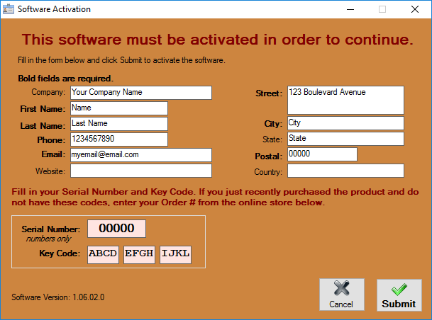
After receiving the Dragon software, all users will have to register the product with their personal identification along with a Dragon Serial number and Keycode (provided).
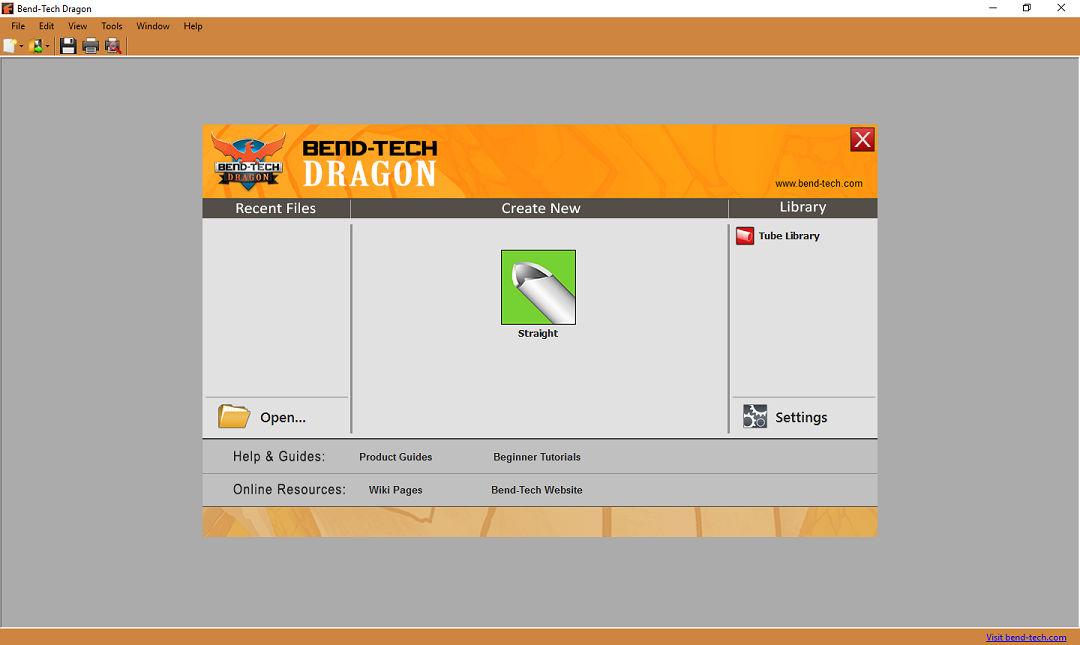
Upon initial startup, the software will display a splash screen and open to the Dragon Task Menu. Here, you will have the options from the Main Menu Bar above along with creating straight parts with the Straight Part coping designer.
Tube Library
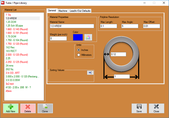
We first advise you to enter material information into the Tube Library (located to the right of the Task Menu screen in the Library section) in order to designate what material you will be working with on a particular job. Only after a material is added to the Tube Library can you create a part in the Straight Part coping designer.
General
Material Properties
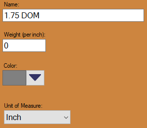
Material Name:
- This title will be used to refer to the material throughout the software. It is recommended to give each a unique, descriptive name to more easily identify each material.
Weight (per inch):
- The weight of the material per unit can be supplied here. This value is completely optional, but it will be used to calculate the total weight of the part in the part designer interfaces above the results table.
Color:
- The color of the material can be chosen using the Color button.
 This color will be used to shade the material in various areas throughout the software.
Type:
- Tube material can be either round, square, or rectangle.
Units:
- Parts can be measured in either inches or millimeters.
Polyline Resolutions:
Max Length:
- This is where the user will enter the maximum length for each segment in a polyline. A segment will be ignored if it is longer than this value. If the segment is shorter, it may be combined with an adjacent segment to create a single segment.
Max Angle:
- This is where the user will enter the maximum angle between two segments in a polyline. If the angle is smaller than this value, the two segments may be combined to create a single segment.
Max Offset:
- This is where the user will enter the maximum boundary offset for a polyline. If the combination of two line segments breaches the boundary defined by this value, the features will not be combined.
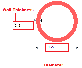
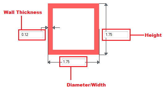
Wall Thickness, Diameter, and Height:
- Depending on the type of material chosen, there will be different dimensions that will need to be supplied. If the material is round or square, the wall thickness and diameter measurements will be required. These values will be entered into the fields on the material diagram. If the material is rectangular, the wall thickness, diameter/width, and height will need to be provided. Note: The diameter/width and height of all materials are measured from the outside edges.
Machine Settings
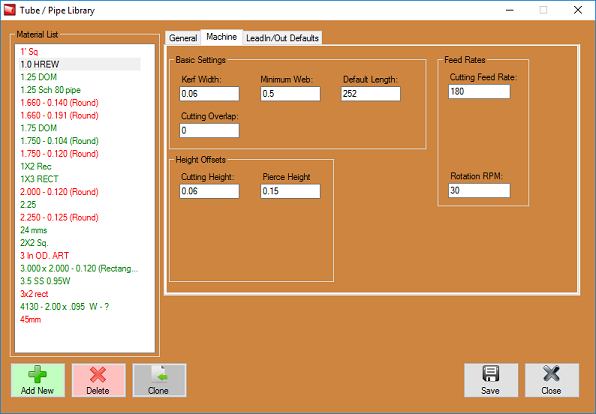
We recommend watching the video at the link below in order to understand what material settings should be applied for a typical entry. This has proven to be very helpful to many of our customers.
Material Machine Settings Video
Standard Material Machine Settings
NOTE: Machine Settings for Dynatorch users will not include the same options for Dragon machine owners. Your settings will only include the following options:
- Kerf Width
- Minimum Web
- Default (stock) Length
- Cutting Overlap
- Cutting Height
- Pierce Height
- Cutting Feed Rate
- Rotation RPM
These settings can be found in your cut charts in your torch manual... Any Thermal Dynamics torch inquiries will be re-directed to the Thermal Dynamics manufacturer as we do not offer technical support on their hardware.
