Main Menu Bar
Bend-Tech 7x Wiki :: Main Menu Bar
![]() At the very top of any of the design window, there is a menu consisting of file, edit, view, tools, window, and help. Click on these menu options to access the drop down menus.
At the very top of any of the design window, there is a menu consisting of file, edit, view, tools, window, and help. Click on these menu options to access the drop down menus.
Contents
- 1 File
- 2 Edit
- 3 View
- 4 Toolbar/Status Bar
- 5 Features
- 6 Mode
- 7 Task Menu
- 8 Tools
- 8.1 Options
- 8.2 Export Template
- 8.3 Die Library
- 8.4 Tube/Pipe Library
- 8.5 Plate/Sheet Library
- 8.6 SpringBack Library
- 8.7 Machine Library
- 8.8 J-Bend Library
- 8.9 Die References
- 8.10 Material References
- 8.11 Bend Mark Settings
- 8.12 Pricing Settings
- 8.13 SW Plugin Settings
- 8.14 User Profile
- 8.15 Backup and Restore
- 8.16 Activate Module
- 8.17 Upgrade Product
- 8.18 Window
- 8.19 Help
- 8.19.1 Visit Wiki Pages
- 8.19.2 Help Guides
- 8.19.3 Browse Guides
- 8.19.4 Trig Calculator
- 8.19.5 Fraction Chart
- 8.19.6 Crown Wizard
- 8.19.7 Apex Finder
- 8.19.8 Chord Calculator
- 8.19.9 Ellipse Length
- 8.19.10 Rise and Run
- 8.19.11 Stair Wizard
- 8.19.12 Support Session
- 8.19.13 Check For Updates
- 8.19.14 About...
File
In the File menu, new files can be created, opened, imported, exported and/or saved, windows can be closed, setup sheets can be printed, and recent files can be accessed.
Open: Part, plate, and assembly files can be opened under the 'Open' option. Place cursor on 'Open' to access each file type. Choose either 'Tube', 'Assembly', 'Plate', 'Header', or 1D Nesting to open a file of the chosen type. Once an option is selected, the Open menu will appear. Choose a file to open and click 'Open' to open it into a design window.
Close: Click the 'Close' option to close the current active window. If the design hasn't been saved yet, a window asking whether to save it or not will display.
Close All: Click the 'Close All' button to close all design windows. If any of designs have not been saved, each un-saved part windows will have a prompt asking whether to save or not. To save it, click 'Yes', give it a name, and click the 'Save' button. Click 'No' to close without saving. Click 'Cancel' to neither close or save.
Save: Click the 'Save' option to save any progress in the current active window. If the design has already been saved, it will be saved to the file it was previously saved in. If the part hasn't been saved previously, the 'Save' menu will appear. Give the design a name and click the 'Save' button.
Save As: Click the 'Save As' option to save the current design in a new file location. The Save menu will open. Give the design a name and click the 'Save' button.
Save All: Click the 'Save All' option to save progress in all open design windows. If any of the designs have not been saved previously, a Save menu will appear for each window. Give the design(s) names and click 'Save'.
Import: Part, assembly, and plate design files can be imported using the 'Import' option. Click the "Import" link for further information on importing designs.
Export: Part, assembly, and plate designs can be exported as Data (.dxf), Bitmap image (.bmp), Template, STEP (.step/.stp), IGES (.iges/.igs), BREP (.brep) files using the 'Export' option. Click the "Export" link for further information on exporting designs.
Convert Files: Here, you can convert files from an older version of the software to the version you're currently on. These files will have to be located on the currently used computer.
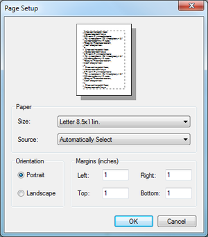
Page Setup: In the page setup menu, the paper size, printer tray, orientation, and margins of the part print out sheets can be defined.
Print: Click the 'Print' option to print out the setup sheet for the current part. To add or remove anything from this page, check/uncheck any of the printing options in the Settings tab in the tabbed section near the upper left corner of the part design frame.
Print Preview: Click the 'Print Preview' option to see a preview of the setup sheet. Use the icons in the top left corner to adjust the zoom and the amount of pages shown. Click the 'Print' button to print the setup sheet. Click 'Close' to close the print preview without printing.
Recent Files: Place the cursor over the 'Recent Files' to see the last 10 files that were opened. To open a file, click the file name. Click 'Clear List' to remove any recent files shown in the list.
Exit: Click the 'Exit' option to completely close out of the software. If any files haven't been saved, a prompt will appear for each unsaved window asking whether to save or not.
Edit
In the Edit menu, the option to undo or redo actions done a Plate or Assembly design window is available. The Edit menu will only be used while a Plate or Assembly design window is in use.
View
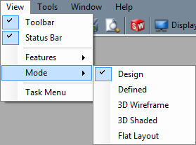
In the View menu, the toolbar, status bar, Plate design features can be hidden/shown and the Plate design mode can be adjusted.
Toolbar/Status Bar
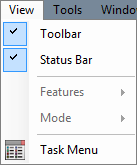
Click on the 'Toolbar' option to either hide or show the toolbar. While a check is displayed next to Toolbar, the icon toolbar at the top of the page will be shown.
Click on the 'Status Bar' option to either hide or show the status bar. While a check is display next to Status Bar, the status bar (XYZ coordinates, date, time, and website link) in the bottom right corner will be displayed.
Features
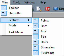
While working in a Plate design window, the option to show or hide certain features in the design window is available. To hide or show a specific feature, place the cursor over 'Features' and click on an option in the menu to either hide or show it. When a checkmark is displayed next to a feature's name, it will be displayed.
Mode
While working in a Plate design window, different modes that effect the display of the part are available. All modes except 'Design' will only work if the part has been successfully defined. See Definition (Part) for information on how to define a part.
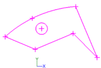
- Design: While 'Design' is selected, the original features used to create the plate will be shown.
- Defined: While 'Defined' is selected, a 2D defined outline of the part's defined features will be displayed.
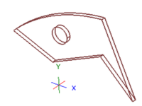
- 3D Wireframe: While '3D Wireframe' is selected, a 3D wireframe version of the part will be displayed.
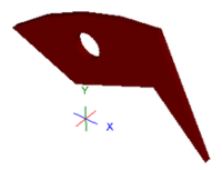
- 3D Shaded: While '3D Shaded' is selected, a solid shaded version of the part will be displayed.
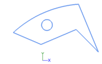
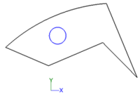
- Flat Layout: While 'Flat Layout' is selected, a flat 2D outline of the part will be displayed.
Task Menu
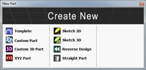
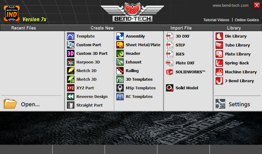
Select the Task Menu option to access the task menu. This menu is used to start new parts, assemblies, plates, import files, view the various data libraries, open files, and open the settings menu. Resources such as manuals, tutorials, and online wiki help can be accessed here as well.
Tools
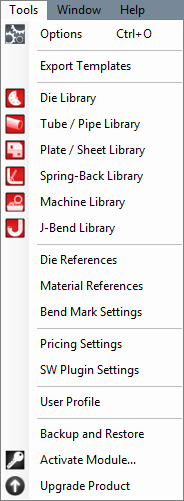
In the Tools menu, the Options Menu, Export Templates, Die Library, Tube/Pipe Library, Plate/Sheet Library, Spring-Back Library, Machine Library, J-Bend Library, Die References, Material References, Bend Mark Settings, Pricing Settings, SW Plugin Settings, User Profile, Backup and Restore, Activate Module and the Upgrade Product menus can be accessed.

Options
Click 'Options' to access the options/settings menu. Follow the "Options" link for further information on each tab in the Options menu.
Export Template
In the Export Template Design menu, the designs of Export Templates can be set up. Follow the "Export Template" link for further information on designing export templates.

Die Library
The die library stores all of the dies that can be used. On the left side of the die library, a list of all available dies is show below 'Die List'. To the right of the list, Die details, die limitations, and user defined definitions are shown.

Tube/Pipe Library
The Tube/Pipe Library holds all the materials that can be used to create bent parts in the part designers.

Plate/Sheet Library
The Plate/Sheet Library holds all materials that can be used to create plate parts.

SpringBack Library
The Spring-Back Library contains all of your entries for spring-back based on your material and dies.

Machine Library
The Machine Library stores all machines that can be used to apply settings to and simulate the bending of a single part.

J-Bend Library
The J-Bend Library stores all J-Bends that can be used to create headers. (This is only available when the Header Module has been purchased.)

Die References
The Die References will associate a selected die with a selected material and will give you the option for setting up CLR tolerances for importing purposes. If the imported part's detected CLR falls within the bounds of the tolerances set up here, then the die will automatically be applied for you. (This is only available in our SE and Industrial products.)

Material References
The Material References will associate a selected material with an imported material. Any imported material, based on material width, height and wall thickness will automatically be changed to the associated material chosen here. (This is available in our SE and Industrial products.)

Bend Mark Settings
The Bend Mark Settings will allow you to set the way in which bend markings will appear on the selected material tube/pipe. This is meant for showing bend markings for a flat layout of the tube project when exporting as a .dxf file or before fabrication with the Dragon machine. (This is only available in our Industrial product.)
Pricing Settings
Once the price settings have been set up, the total cost of a part, plate, or assembly, including labor, setup time, time per bend, and cost per unit, can be determined and shown in the Assembly interface. (This is only available in our SE product.)
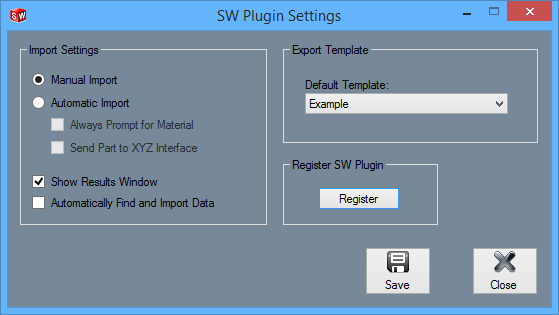
SW Plugin Settings
Import Settings
Manual Import: This option makes it so SolidWorks files need to be defined manually before being fully imported once they have been sent to Bend-Tech.
Automatic Import: While this option is enabled, Bend-Tech will attempt to automatically define and import all SolidWorks files that have been sent to Bend-Tech. If Automatic Import is selected and Always Prompt for Material is checked, every time a SolidWorks file is automatically imported, a material must be chosen for the part. If Automatic Import is selected and Send Part to XYZ Interface is checked, once SolidWorks parts are imported, they will be sent to the XYZ part design interface.
Show Results Window: Check this option to open the Part Details window once the part has been fully imported.
Automatically Find and Import Data: Check this option to have SolidWorks parts automatically brought into the import interface once a part has been send to Bend-Tech without having to click the SolidWorks icon at the top of the window or File - Import - SolidWorks.
Export Template
The default export template design can be set here. Export templates are defined in the Export Template designer. This template will be the export template that is initially chosen when the Part Details window shows up. To change the export template, click the drop down menu and select an option from the list.
Register SW Plugin
This button is used to register an SW module after it has been activated using Activate Module.
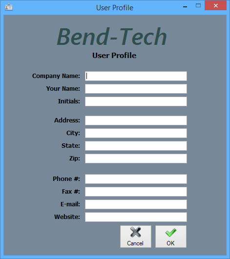
User Profile
Entering information in the User Profile allows the user to have their information attached to the software. The initials given here will be printed on any setup sheets that are printed out.
To add or change any of the user profile information, simply enter a new definition for any of the available fields. Click 'OK' to save and exit. Click 'Cancel' to exit without saving any entered information.
Backup and Restore
The software can backup and/or restore all the data libraries, part files, assembly files, favorite templates, user profile, export templates, and program settings.
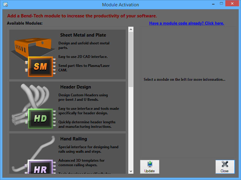
Activate Module
Sheet Metal, Header Design, SolidWorks, Hand Railing, and Large Radius Bending modules can be activated using this menu. To activate a module, select the module from the list on the left by clicking on it. Enter the activation code and click the Activate button to confirm. Lastly, click the Update button to update the software with the new module(s).
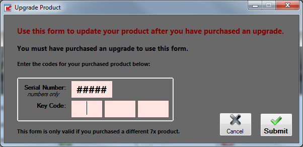
Upgrade Product
After purchasing an upgrade for your Bend-Tech software, it can be updated using this form. The Serial Number and Key Code are required to successfully upgrade.
Window
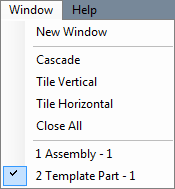
The Window menu contains options for window display and arrangement.
The Window menu contains options for window display and arrangement.
New Window: Click the 'New Window' option to bring up the Task Menu.
Cascade: Click the 'Cascade' option to have all open windows shrunk and layered in the top left corner of the frame. See the picture below for an example.
Tile Vertical: Click 'Tile Horizontal' to have all the currently open windows layered on top of one another from the top to the bottom of the main window.
Tile Horizontal: Click 'Tile Vertical' to have all the currently open windows layered on top of one another from left to right.
Close All: Click the 'Close All' option to close all currently open windows. If any open windows have not been save previous to clicking this option, a prompt for each unsaved design will appear asking to save it or not.
Part List: At the bottom of the Window menu, a list of all opens windows will be shown. A check will be shown next to the part, plate, or assembly design that is currently in front. To bring a different part design to the top of all other windows, click on the design name.
Help
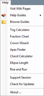
In the Help menu, help guides, Trig and chord calculators, the fraction chart, apex finder, crown wizard, and ellipse length finder can be accessed.
In the Help menu, help guides, Trig and chord calculators, the fraction chart, apex finder, crown wizard, and ellipse length finder can be accessed.
Visit Wiki Pages
Click this option to open this wiki webpage in a new browser window.
Help Guides
To view a list of all the guides and tutorials, place the cursor over the 'Help Guides' option. Click on any of the options in this list to access the chosen guide or tutorial in a pdf format.
Browse Guides
Click the 'Browse Guides' option to open the directory where all the help guides are located.
Trig Calculator
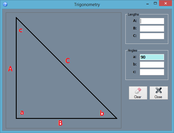
Click the 'Trig Calculator' option for help on calculating the lengths and/or angles of a right triangle. Enter at least one angle and one length or two lengths to find the total set of lengths and dimensions for the triangle. Click the 'Clear' button to clear out all entered values. Click 'Close' to exit the Trig Calculator.
Fraction Chart
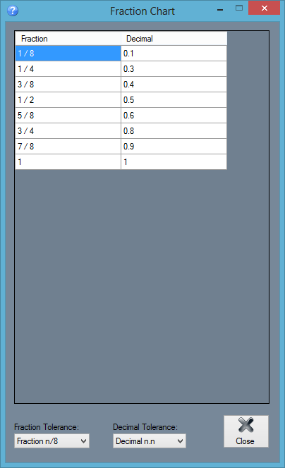
Click the 'Fraction Chart' option to access a chart of fraction and decimal comparison chart. The first column will contain a list of fractions and the second column will contain a list of the equivalent decimal values. The fraction column can be adjusted by selecting a new fraction tolerance from the 'Fraction Tolerance' drop down menu. For example, if 'n/16' is chosen, the fraction column will start at 1/16 and be incremented by 1/16 until it reaches 1 at the bottom of the column. The precision or tolerance of the decimal column can be adjusted by selecting a new tolerance from the 'Decimal Tolerance' drop down menu. In both of the 'Fraction Tolerance' and 'Decimal Tolerance' drop down menus, the 'n' represents a digit placement.
Crown Wizard
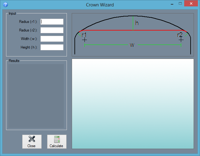
Click the 'Crown Wizard' option to calculate the part details/measurements of a part that has a crown to the top a straight section between two bends. To do so, enter the radius of the first bend and second bend, the width from the center of the first bend to the center of the second bend, and the desired height of the crown into the appropriate fields below 'Input'. See the provided diagram in the Crown Wizard frame for help on where to get the proper measurements. Once both radii, the width, and height are entered, click 'Calculate' to bring up the results. Once clicked, the crown dimensions/measurements will be shown below 'Results' along with a preview of the crown part to the right. Use the mouse scroll wheel to zoom in and out out of the preview - scroll up to zoom out and scroll down to zoom in. To move/pan the preview, click and hold the scroll wheel or both mouse buttons and move the cursor around.
Apex Finder
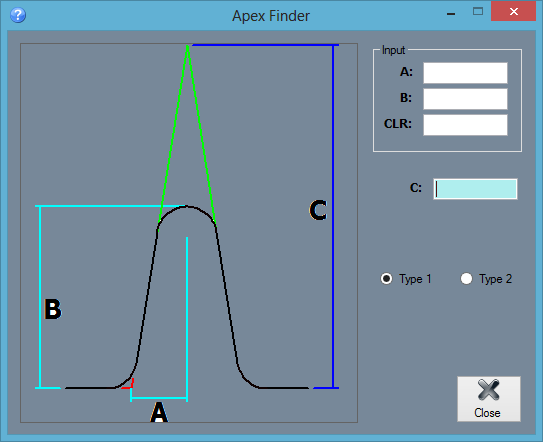
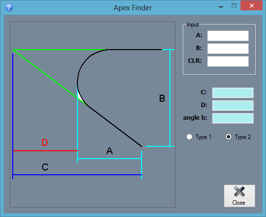
Click the 'Apex Finder' option to open the Apex Finder menu.
- Type 1: To calculate the distance from the apex of the previous bend to the current bend's apex click the circle next to 'Type 1'. To able able to use Type 1, at least two bends are needed.The A length is the measurement from the center of the bend to the apex of the previous or next bend. The B length is the measurement from the top of the centerline of the bend to the apex of the previous or next bend. See the diagram used in the Apex Finder window for a better explanation on how to acquire these lengths. Once A and B have been found, enter these values into the 'A' and 'B' fields along with the Centerline radius of the bend in the 'CLR' field. Once entered, the final C length will be shown in the field next to 'C'.
- Type 2: To calculate the angle of the apex, the length from the apex to the end of the bend leg, and the distance from the top of the bend's centerline to the apex, click the circle next to 'Type 2'. The only necessary features are a bend and two legs. The A length is the distance from the centerline of the top of the bend to the end of the leg. The B length is the distance between the centerline of one leg to the other. See the diagram supplied for a more accurate representation of how to acquire these measurements. Once these measurements have been found, enter the A value into the 'A' field, the B value into the 'B' field, and the centerline radius of the bend in the 'CLR' field. Once these values have been supplied, the C, D, and angle b values will be shown in the fields below. The C length is the distance from the apex to the end of the bend leg, the D length is the distance from the the top of the bend's centerline to the apex, and the angle b value is the angle of the apex.
Chord Calculator
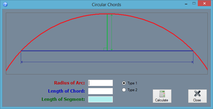
- Type 1: To calculate the length of the segment by giving the radius of the arc and the length of the chord, click the circle next to 'Type 1'. The radius of the arc (red line) is the distance between the center of the arc and the top of the arc. The length of the chord (blue line) is the distance between each leg of the arc. Enter each value into the appropriate fields next to 'Radius of Arc' and 'Length of Chord'. Click the 'Calculate' button to generate the length of the segment (green line) in the 'Length of Segment' field.
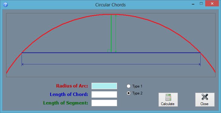
- Type 2: To calculate the radius of the arc by giving the length of the chord and the length of segment, click the circle next to 'Type 2'. The length of the segment (green line) is the distance from the top center of the arc to the chord. The length of the chord (blue line) is the distance between each leg of the arc. Enter each of the values in the appropriate fields next to 'Length of segment' and 'Length of Chord'. Click the 'Calculate' button to generate the radius in the 'Radius of Arc' field.
Ellipse Length
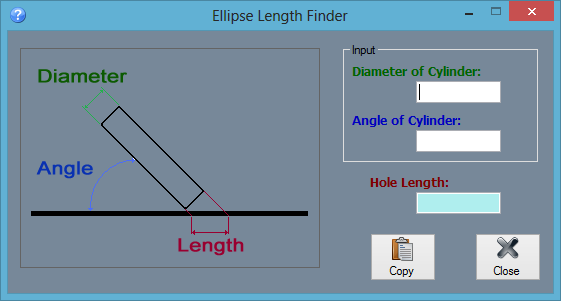
Available for the PRO product or higher click the 'Ellipse Length' to access the Ellipse Length Finder menu. This calculator determines the length of an elliptical hole created by using a cylinder of a certain diameter pushed through the material at a specific angle. Enter the diameter of the cylinder into the field below 'Diameter of Cylinder' and the angle that the cylinder was pushed into the material at in the field below 'Angle of Cylinder'. Once both of these values have been supplied, the length of the hole will be shown in the 'Hole Length' field. To copy the hole value to the clipboard, click the 'Copy' button.
Rise and Run
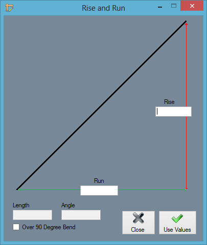
Available for the SE software product or higher. This calculator determines the length and angle of a line based on a given rise and run value. Enter the Rise and Run values in the fields. The Length and angle values will be generated in the fields below. For angles over 90 degree, check the Over 90 Degree Bend box. Note: Clicking the Use Values button will not affect any open part designs.
Stair Wizard
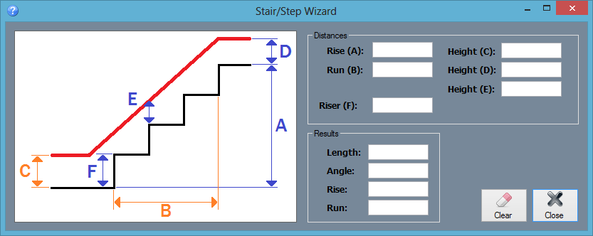
This calculator is similar to the Rise and Run calculator, but it determines rise, run, length and angle and is available for users with the Handrail Module.
Support Session
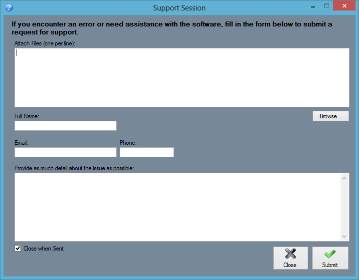
If you encounter any difficulties working with the software or need help with a specific feature, send a Support Session. Attach the part, assembly, or plate files that are related to the issue at hand, if applicable. Provide a full name, email, and phone number and an explanation of the issue. Click the Submit button to send the request to the Bend-Tech support team.
Check For Updates
To manually check for software updates, select this option and the software will search for and apply any updates.
About...
Click the 'About...' option to access some basic information about the software. This window will contain which version of the software is in use and contact information for either support or sales inquiries.

