Difference between revisions of "Help"
| (One intermediate revision by the same user not shown) | |||
| Line 21: | Line 21: | ||
<h4>Trig Calculator</h4> | <h4>Trig Calculator</h4> | ||
| − | [[File: | + | [[File:trig_calc1.png|right]] |
Click the 'Trig Calculator' option for help on calculating the lengths and/or angles of a right triangle. Enter at least one angle and one length or two lengths to find the total set of lengths and dimensions for the triangle. Click the 'Clear' button to clear out all entered values. Click 'Close' to exit the Trig Calculator. | Click the 'Trig Calculator' option for help on calculating the lengths and/or angles of a right triangle. Enter at least one angle and one length or two lengths to find the total set of lengths and dimensions for the triangle. Click the 'Clear' button to clear out all entered values. Click 'Close' to exit the Trig Calculator. | ||
| Line 44: | Line 44: | ||
<h4>Fraction Chart</h4> | <h4>Fraction Chart</h4> | ||
| − | [[File: | + | [[File:fraction_chart1.png|right]] |
Click the 'Fraction Chart' option to access a chart of fraction and decimal comparison chart. The first column will contain a list of fractions and the second column will contain a list of the equivalent decimal values. The fraction column can be adjusted by selecting a new fraction tolerance from the 'Fraction Tolerance' drop down menu. For example, if 'n/16' is chosen, the fraction column will start at 1/16 and be incremented by 1/16 until it reaches 1 at the bottom of the column. The precision or tolerance of the decimal column can be adjusted by selecting a new tolerance from the 'Decimal Tolerance' drop down menu. In both of the 'Fraction Tolerance' and 'Decimal Tolerance' drop down menus, the 'n' represents a digit placement. | Click the 'Fraction Chart' option to access a chart of fraction and decimal comparison chart. The first column will contain a list of fractions and the second column will contain a list of the equivalent decimal values. The fraction column can be adjusted by selecting a new fraction tolerance from the 'Fraction Tolerance' drop down menu. For example, if 'n/16' is chosen, the fraction column will start at 1/16 and be incremented by 1/16 until it reaches 1 at the bottom of the column. The precision or tolerance of the decimal column can be adjusted by selecting a new tolerance from the 'Decimal Tolerance' drop down menu. In both of the 'Fraction Tolerance' and 'Decimal Tolerance' drop down menus, the 'n' represents a digit placement. | ||
| Line 71: | Line 71: | ||
<h4>Crown Wizard</h4> | <h4>Crown Wizard</h4> | ||
| − | [[File: | + | [[File:crown_wizard1.png|right]] |
Click the 'Crown Wizard' option to calculate the part details/measurements of a part that has a crown to the top a straight section between two bends. To do so, enter the radius of the first bend and second bend, the width from the center of the first bend to the center of the second bend, and the desired height of the crown into the appropriate fields below 'Input'. See the provided diagram in the Crown Wizard frame for help on where to get the proper measurements. Once both radii, the width, and height are entered, click 'Calculate' to bring up the results. Once clicked, the crown dimensions/measurements will be shown below 'Results' along with a preview of the crown part to the right. Use the mouse scroll wheel to zoom in and out out of the preview - scroll up to zoom out and scroll down to zoom in. To move/pan the preview, click and hold the scroll wheel or both mouse buttons and move the cursor around. | Click the 'Crown Wizard' option to calculate the part details/measurements of a part that has a crown to the top a straight section between two bends. To do so, enter the radius of the first bend and second bend, the width from the center of the first bend to the center of the second bend, and the desired height of the crown into the appropriate fields below 'Input'. See the provided diagram in the Crown Wizard frame for help on where to get the proper measurements. Once both radii, the width, and height are entered, click 'Calculate' to bring up the results. Once clicked, the crown dimensions/measurements will be shown below 'Results' along with a preview of the crown part to the right. Use the mouse scroll wheel to zoom in and out out of the preview - scroll up to zoom out and scroll down to zoom in. To move/pan the preview, click and hold the scroll wheel or both mouse buttons and move the cursor around. | ||
| Line 88: | Line 88: | ||
| − | ::[[File: | + | ::[[File:apex_11.png]] |
*'''Type 2''': To calculate the angle of the apex, the length from the apex to the end of the bend leg, and the distance from the top of the bend's centerline to the apex, click the circle next to 'Type 2'. The only necessary features are a bend and two legs. The A length is the distance from the centerline of the top of the bend to the end of the leg. The B length is the distance between the centerline of one leg to the other. See the diagram supplied for a more accurate representation of how to acquire these measurements. Once these measurements have been found, enter the A value into the 'A' field, the B value into the 'B' field, and the centerline radius of the bend in the 'CLR' field. Once these values have been supplied, the C, D, and angle b values will be shown in the fields below. The C length is the distance from the apex to the end of the bend leg, the D length is the distance from the the top of the bend's centerline to the apex, and the angle b value is the angle of the apex. | *'''Type 2''': To calculate the angle of the apex, the length from the apex to the end of the bend leg, and the distance from the top of the bend's centerline to the apex, click the circle next to 'Type 2'. The only necessary features are a bend and two legs. The A length is the distance from the centerline of the top of the bend to the end of the leg. The B length is the distance between the centerline of one leg to the other. See the diagram supplied for a more accurate representation of how to acquire these measurements. Once these measurements have been found, enter the A value into the 'A' field, the B value into the 'B' field, and the centerline radius of the bend in the 'CLR' field. Once these values have been supplied, the C, D, and angle b values will be shown in the fields below. The C length is the distance from the apex to the end of the bend leg, the D length is the distance from the the top of the bend's centerline to the apex, and the angle b value is the angle of the apex. | ||
| − | ::[[File: | + | ::[[File:apex_21.png]] |
| Line 100: | Line 100: | ||
*'''Type 1:''' To calculate the length of the segment by giving the radius of the arc and the length of the chord, click the circle next to 'Type 1'. The radius of the arc (red line) is the distance between the center of the arc and the top of the arc. The length of the chord (blue line) is the distance between each leg of the arc. Enter each value into the appropriate fields next to 'Radius of Arc' and 'Length of Chord'. Click the 'Calculate' button to generate the length of the segment (green line) in the 'Length of Segment' field. | *'''Type 1:''' To calculate the length of the segment by giving the radius of the arc and the length of the chord, click the circle next to 'Type 1'. The radius of the arc (red line) is the distance between the center of the arc and the top of the arc. The length of the chord (blue line) is the distance between each leg of the arc. Enter each value into the appropriate fields next to 'Radius of Arc' and 'Length of Chord'. Click the 'Calculate' button to generate the length of the segment (green line) in the 'Length of Segment' field. | ||
| − | ::[[File: | + | ::[[File:chord_11.png]] |
*'''Type 2:''' To calculate the radius of the arc by giving the length of the chord and the length of segment, click the circle next to 'Type 2'. The length of the segment (green line) is the distance from the top center of the arc to the chord. The length of the chord (blue line) is the distance between each leg of the arc. Enter each of the values in the appropriate fields next to 'Length of segment' and 'Length of Chord'. Click the 'Calculate' button to generate the radius in the 'Radius of Arc' field. | *'''Type 2:''' To calculate the radius of the arc by giving the length of the chord and the length of segment, click the circle next to 'Type 2'. The length of the segment (green line) is the distance from the top center of the arc to the chord. The length of the chord (blue line) is the distance between each leg of the arc. Enter each of the values in the appropriate fields next to 'Length of segment' and 'Length of Chord'. Click the 'Calculate' button to generate the radius in the 'Radius of Arc' field. | ||
| − | ::[[File: | + | ::[[File:chord_21.png]] |
| Line 116: | Line 116: | ||
Click the 'Ellipse Length' to access the Ellipse Length Finder menu. This calculator determines the length of an elliptical hole created by using a cylinder of a certain diameter pushed through the material at a specific angle. Enter the diameter of the cylinder into the field below 'Diameter of Cylinder' and the angle that the cylinder was pushed into the material at in the field below 'Angle of Cylinder'. Once both of these values have been supplied, the length of the hole will be shown in the 'Hole Length' field. To copy the hole value to the clipboard, click the 'Copy' button. | Click the 'Ellipse Length' to access the Ellipse Length Finder menu. This calculator determines the length of an elliptical hole created by using a cylinder of a certain diameter pushed through the material at a specific angle. Enter the diameter of the cylinder into the field below 'Diameter of Cylinder' and the angle that the cylinder was pushed into the material at in the field below 'Angle of Cylinder'. Once both of these values have been supplied, the length of the hole will be shown in the 'Hole Length' field. To copy the hole value to the clipboard, click the 'Copy' button. | ||
| − | [[File: | + | [[File:ellipse_11.png]] |
| Line 123: | Line 123: | ||
This calculator determines the length and angle of a line based on a given rise and run value. Enter the Rise and Run values in the fields. The Length and angle values will be generated in the fields below. For angles over 90 degree, check the Over 90 Degree Bend box. ''Note: Clicking the '''Use Values''' button will not affect any open part designs.'' | This calculator determines the length and angle of a line based on a given rise and run value. Enter the Rise and Run values in the fields. The Length and angle values will be generated in the fields below. For angles over 90 degree, check the Over 90 Degree Bend box. ''Note: Clicking the '''Use Values''' button will not affect any open part designs.'' | ||
| − | [[File: | + | [[File:rise_and_run1.png]] |
| Line 137: | Line 137: | ||
If you encounter any difficulties working with the software or need help with a specific feature, send a '''Support Session'''. Attach the part, assembly, or plate files that are related to the issue at hand, if applicable. Provide a full name, email, and phone number and an explanation of the issue. Click the '''Submit''' button to send the request to the Bend-Tech support team. | If you encounter any difficulties working with the software or need help with a specific feature, send a '''Support Session'''. Attach the part, assembly, or plate files that are related to the issue at hand, if applicable. Provide a full name, email, and phone number and an explanation of the issue. Click the '''Submit''' button to send the request to the Bend-Tech support team. | ||
| − | [[File: | + | [[File:support_sessions1.png]] |
| Line 149: | Line 149: | ||
Click the 'About...' option to access some basic information about the software. This window will contain which version of the software is in use and contact information for either support or sales inquiries. | Click the 'About...' option to access some basic information about the software. This window will contain which version of the software is in use and contact information for either support or sales inquiries. | ||
| − | [[File: | + | [[File:about1.png]] |
Latest revision as of 13:12, 29 September 2014
Bend-Tech 7x Wiki :: Main Menu Bar :: Help
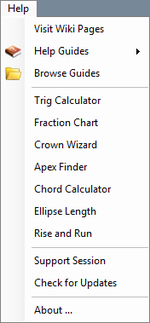
In the Help menu, help guides, Trig and chord calculators, the fraction chart, apex finder, crown wizard, and ellipse length finder can be accessed.
Visit Wiki Pages
Click this option to open this wiki webpage in a new browser window.
Help Guides
To view a list of all the guides and tutorials, place the cursor over the 'Help Guides' option. Click on any of the options in this list to access the chosen guide or tutorial in a pdf format.
Browse Guides
Click the 'Browse Guides' option to open the directory where all the help guides are located.
Trig Calculator
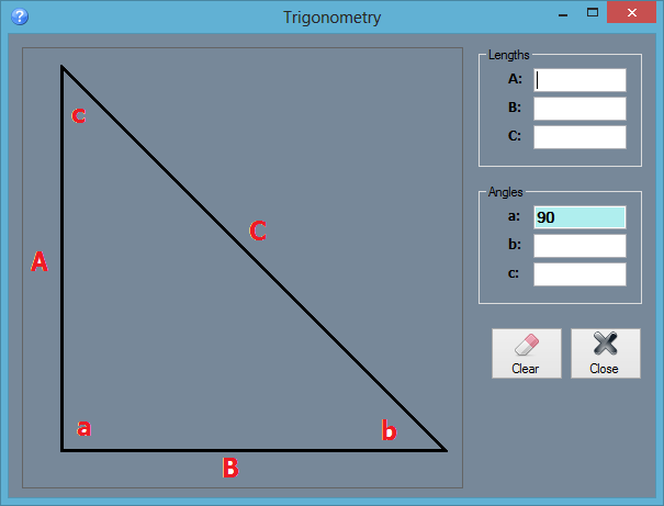
Click the 'Trig Calculator' option for help on calculating the lengths and/or angles of a right triangle. Enter at least one angle and one length or two lengths to find the total set of lengths and dimensions for the triangle. Click the 'Clear' button to clear out all entered values. Click 'Close' to exit the Trig Calculator.
Fraction Chart
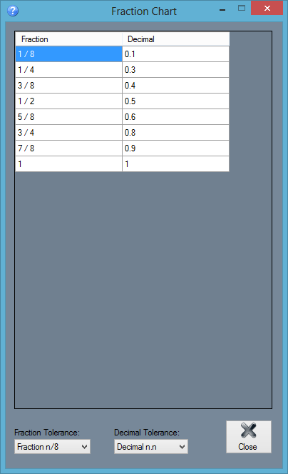
Click the 'Fraction Chart' option to access a chart of fraction and decimal comparison chart. The first column will contain a list of fractions and the second column will contain a list of the equivalent decimal values. The fraction column can be adjusted by selecting a new fraction tolerance from the 'Fraction Tolerance' drop down menu. For example, if 'n/16' is chosen, the fraction column will start at 1/16 and be incremented by 1/16 until it reaches 1 at the bottom of the column. The precision or tolerance of the decimal column can be adjusted by selecting a new tolerance from the 'Decimal Tolerance' drop down menu. In both of the 'Fraction Tolerance' and 'Decimal Tolerance' drop down menus, the 'n' represents a digit placement.
Crown Wizard
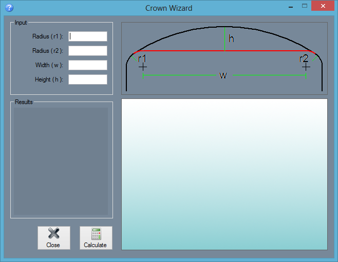
Click the 'Crown Wizard' option to calculate the part details/measurements of a part that has a crown to the top a straight section between two bends. To do so, enter the radius of the first bend and second bend, the width from the center of the first bend to the center of the second bend, and the desired height of the crown into the appropriate fields below 'Input'. See the provided diagram in the Crown Wizard frame for help on where to get the proper measurements. Once both radii, the width, and height are entered, click 'Calculate' to bring up the results. Once clicked, the crown dimensions/measurements will be shown below 'Results' along with a preview of the crown part to the right. Use the mouse scroll wheel to zoom in and out out of the preview - scroll up to zoom out and scroll down to zoom in. To move/pan the preview, click and hold the scroll wheel or both mouse buttons and move the cursor around.
Apex Finder
Click the 'Apex Finder' option to open the Apex Finder menu.
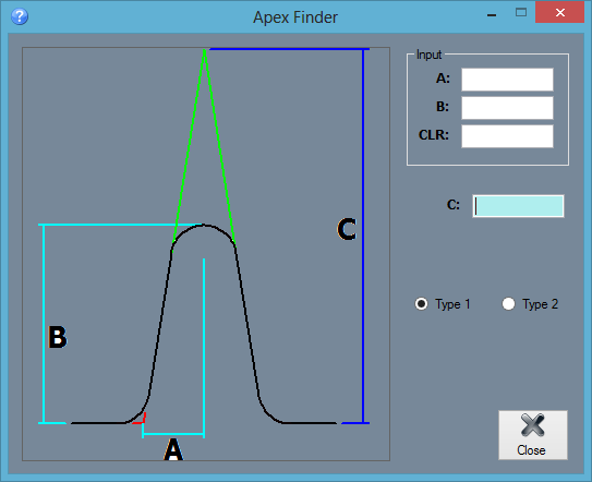
- Type 1: To calculate the distance from the apex of the previous bend to the current bend's apex click the circle next to 'Type 1'. To able able to use Type 1, at least two bends are needed.The A length is the measurement from the center of the bend to the apex of the previous or next bend. The B length is the measurement from the top of the centerline of the bend to the apex of the previous or next bend. See the diagram used in the Apex Finder window for a better explanation on how to acquire these lengths. Once A and B have been found, enter these values into the 'A' and 'B' fields along with the Centerline radius of the bend in the 'CLR' field. Once entered, the final C length will be shown in the field next to 'C'.
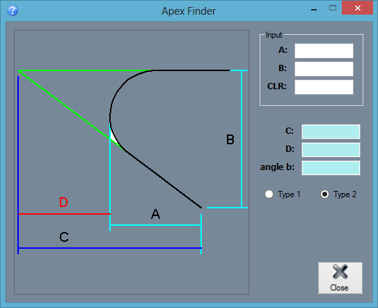
- Type 2: To calculate the angle of the apex, the length from the apex to the end of the bend leg, and the distance from the top of the bend's centerline to the apex, click the circle next to 'Type 2'. The only necessary features are a bend and two legs. The A length is the distance from the centerline of the top of the bend to the end of the leg. The B length is the distance between the centerline of one leg to the other. See the diagram supplied for a more accurate representation of how to acquire these measurements. Once these measurements have been found, enter the A value into the 'A' field, the B value into the 'B' field, and the centerline radius of the bend in the 'CLR' field. Once these values have been supplied, the C, D, and angle b values will be shown in the fields below. The C length is the distance from the apex to the end of the bend leg, the D length is the distance from the the top of the bend's centerline to the apex, and the angle b value is the angle of the apex.
Chord Calculator
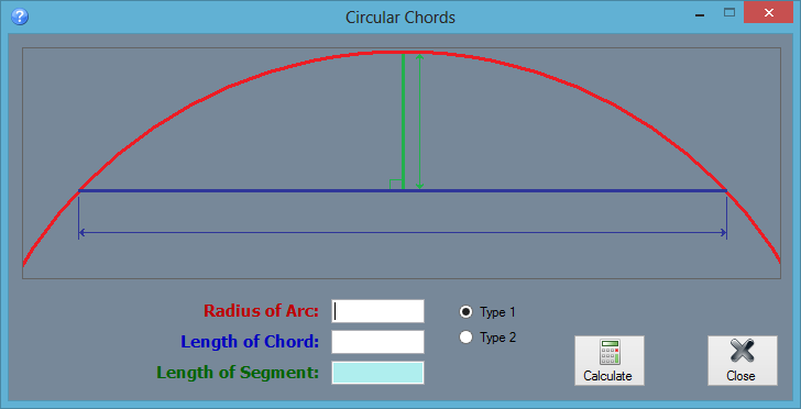
- Type 1: To calculate the length of the segment by giving the radius of the arc and the length of the chord, click the circle next to 'Type 1'. The radius of the arc (red line) is the distance between the center of the arc and the top of the arc. The length of the chord (blue line) is the distance between each leg of the arc. Enter each value into the appropriate fields next to 'Radius of Arc' and 'Length of Chord'. Click the 'Calculate' button to generate the length of the segment (green line) in the 'Length of Segment' field.
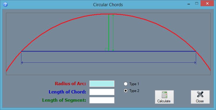
- Type 2: To calculate the radius of the arc by giving the length of the chord and the length of segment, click the circle next to 'Type 2'. The length of the segment (green line) is the distance from the top center of the arc to the chord. The length of the chord (blue line) is the distance between each leg of the arc. Enter each of the values in the appropriate fields next to 'Length of segment' and 'Length of Chord'. Click the 'Calculate' button to generate the radius in the 'Radius of Arc' field.
Ellipse Length
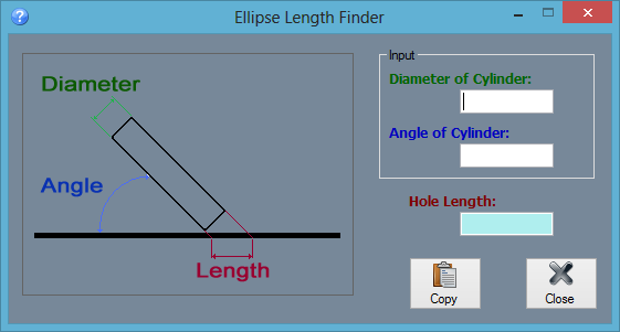
Click the 'Ellipse Length' to access the Ellipse Length Finder menu. This calculator determines the length of an elliptical hole created by using a cylinder of a certain diameter pushed through the material at a specific angle. Enter the diameter of the cylinder into the field below 'Diameter of Cylinder' and the angle that the cylinder was pushed into the material at in the field below 'Angle of Cylinder'. Once both of these values have been supplied, the length of the hole will be shown in the 'Hole Length' field. To copy the hole value to the clipboard, click the 'Copy' button.
Rise and Run
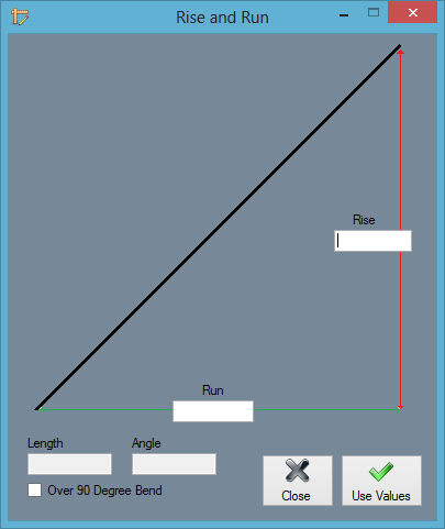
This calculator determines the length and angle of a line based on a given rise and run value. Enter the Rise and Run values in the fields. The Length and angle values will be generated in the fields below. For angles over 90 degree, check the Over 90 Degree Bend box. Note: Clicking the Use Values button will not affect any open part designs.
Stair Wizard
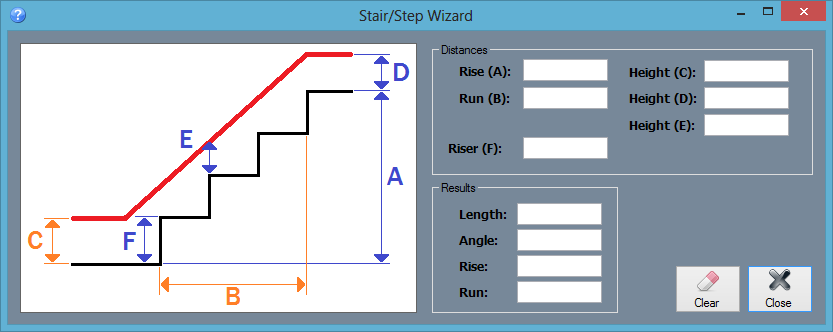
This calculator is similar to the Rise and Run calculator, but it determines rise, run, length and angle and is geared towards the user of the Handrail Module.
Support Session
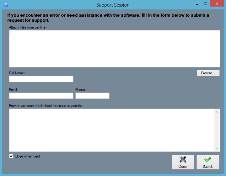
If you encounter any difficulties working with the software or need help with a specific feature, send a Support Session. Attach the part, assembly, or plate files that are related to the issue at hand, if applicable. Provide a full name, email, and phone number and an explanation of the issue. Click the Submit button to send the request to the Bend-Tech support team.
Check For Updates
To manually check for software updates, select this option and the software will search for and apply any updates.
About...
Click the 'About...' option to access some basic information about the software. This window will contain which version of the software is in use and contact information for either support or sales inquiries.
