Difference between revisions of "Custom 3D Part"
| Line 34: | Line 34: | ||
| − | [[File:custom3d_4.png|right | + | [[File:custom3d_4.png|right]] |
In summary, by '''typing values''' directly into the fields, the part will begin to take shape. | In summary, by '''typing values''' directly into the fields, the part will begin to take shape. | ||
| Line 70: | Line 70: | ||
| − | [[File:custom3d_5.png|right | + | [[File:custom3d_5.png|right]] |
*'''Each bend can be assigned a die''' by selecting the bend number in the bend list and selecting a die or custom CLR from the '''Die''' drop down menu. Each bend can also be assigned to a dimension type by selecting a bend from the bend list and selecting either Apex or Tangent from the drop down menu next to 'Dim Type:'. | *'''Each bend can be assigned a die''' by selecting the bend number in the bend list and selecting a die or custom CLR from the '''Die''' drop down menu. Each bend can also be assigned to a dimension type by selecting a bend from the bend list and selecting either Apex or Tangent from the drop down menu next to 'Dim Type:'. | ||
*'''Apex''' will measure to the outside intersection (apex) of the bends two legs. '''Tangent''' will measure to the edge of the bends, the tangents, so no bent material will be included in the measurements. See images below. | *'''Apex''' will measure to the outside intersection (apex) of the bends two legs. '''Tangent''' will measure to the edge of the bends, the tangents, so no bent material will be included in the measurements. See images below. | ||
::[[File:apex.png|200px]] [[File:tangent.png|186px]] | ::[[File:apex.png|200px]] [[File:tangent.png|186px]] | ||
Latest revision as of 13:10, 27 January 2015
Bend-Tech 7x Wiki :: Custom 3D Part
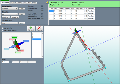
- Custom 3-dimensional parts can be created by entering ceiling/floor, left/right, and back/front coordinates, by using the 3D angle interface, or by drawing out the part by dragging the harpoon bend tool.
Selection
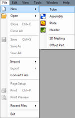
To create a Custom 3D Part:1.) Go to the File menu, select New, then select Tube. In the Create New menu, select the Custom 3D Part option.
2.) Select the New Part icon and select the Custom 3D Part option in theCreate New menu.
...OR
3.) Select the Custom 3D Part option from the Task Menu that appears when the software starts up, when all designs are closed, or through the view menu.
Design
- Once Custom 3D Part is selected, a new custom 3D part design window will open. If a default die and material have not been set, a die and material must be chosen before designing the part. If necessary, choose a material, die, and/or machine in the Die and Material tab. Once a die and material are selected, the custom 3D part design section will appear.
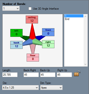
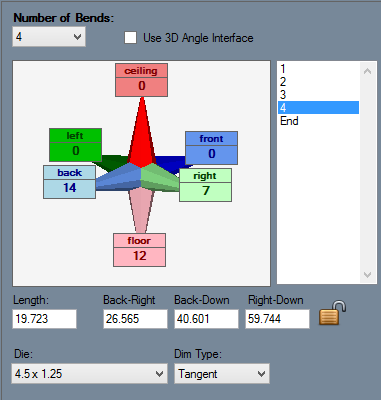
- The Tri-star value section to the left of the display area is where the user can type in leg lengths in any direction.
- To start designing the part, first select the number of bends that the part will have. The first straight length of part will be designed once the user has entered a value into a directional value field on the Tri-star to the left.
- (Note) A single straight length can be created in 3 total directions. For example, if the dark green field is filled in, the light green will not be available to enter values into. In the designer entry fields, if the light blue field has a value of 500, it will be set to 0 if any values are entered in the dark blue field.
In summary, by typing values directly into the fields, the part will begin to take shape.
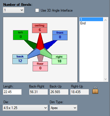
- As the part is being drawn, the lengths, angles and rotations will be automatically generated in the designer entry fields on the left of the screen. The values in the colored fields show how far and in which direction the current length of tube has been moved.
- Once more than one angle is applied to a bend (Example: You've entered a number into the light green value field and then the red value field within the same length of tubing), the angle as well as the axis that the angle is along will be shown below the value fields in the left panel next to an axis icon. These angle values can be also edited by typing values directly into the given fields.
- If more than two angles are added to the bend, two more angle values will be generated. These can also be edited by directly typing values into the fields.
- Individual bend angles can be locked by selecting and toggling the lock icon on
 or off
  . When a bend is locked, the angles of the bend will be locked in place if any attempts to change them are made.
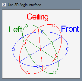
- Check the "Use 3D Angle Interface" check box to use the 3D coordinate interface with the currently selected bend.
- The blue, red, and green circles each represent a plane or dimension- the green section is the right/left plane, the red section runs from the ceiling to the floor, and the blue section is the front/back plane.
- Each of these planes has four white points separated by 90 degrees around the edge.
- To enter coordinates while in the 3D Angle Interface, select the bend and select one of the white points on a plane to choose a direction. Once a direction is chosen, enter any necessary values into the Angle and Length, Ceiling, Floor, Back, Front, Left, or Right fields that appear below the compass. Only one of these three fields to the right of the 'Angle' field can have a value at a time. For example, if a value is entered into 'Length' field while the 'Back' field has a value, the 'Back' field will be set to a zero.
- To rotate the compass, click and hold the right mouse button and move the cursor to rotate.
- Each bend can be assigned a die by selecting the bend number in the bend list and selecting a die or custom CLR from the Die drop down menu. Each bend can also be assigned to a dimension type by selecting a bend from the bend list and selecting either Apex or Tangent from the drop down menu next to 'Dim Type:'.
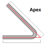
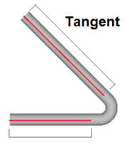
- Apex will measure to the outside intersection (apex) of the bends two legs. Tangent will measure to the edge of the bends, the tangents, so no bent material will be included in the measurements. See images below.
