Difference between revisions of "Dragon Calibration"
| (78 intermediate revisions by the same user not shown) | |||
| Line 1: | Line 1: | ||
| − | '''"This guide will help you understand all of the processes and procedures involved in | + | '''"This guide will help you understand all of the processes and procedures involved in calibrating your Dragon Software to your machine."''' |
| − | '''"Please take your time in | + | '''"Please take your time in calibrating your new Dragon Machine/Software by following all of these steps thoroughly. This should take anywhere from 2-3 hours based on how you pay attention to detail, how much help you have and if you are technologically adept or not."''' |
| − | ''' | + | =Machine Library/Machine Setup= |
| + | *After opening the Bend-Tech CAM software, choose either one of these steps to enter the machine calibration page. | ||
| + | |||
| + | '''1.''' Click directly on the '''Machine Library''' [[File:Mach_Lib_Icon1.png]] icon from the right hand side of the '''[[Task Menu]]''' screen and select the '''Wizard''' [[File:Drag_Calibration_Help1.png]] button. | ||
| + | |||
| + | [[File:Drag_Tools_Mach_Lib1.png]] [[File:Drag_Tools_Mach_Setup1.png]] | ||
| + | |||
| + | '''2.''' Click on the '''Tools''' button from the '''[[Main Menu Bar]]''', then the '''Machine Library''' [[File:Mach_Lib_Icon1.png]] icon and select the '''Wizard''' [[File:Drag_Calibration_Help1.png]] button. | ||
| + | |||
| + | '''3.''' Click on the '''Tools''' button from the '''[[Main Menu Bar]]''', then the '''Machine Setup''' button. | ||
| + | |||
| + | =Dragon Calibration Wizard= | ||
| + | '''This initial startup screen for the Calibration Wizard will allow you to choose from multiple options for calibrating different aspects of your machine, or complete an overall calibration from the beginning.''' | ||
| + | |||
| + | [[File:Dragon_Calibration_Wizard1.png|center]] | ||
=Introduction= | =Introduction= | ||
[[File:Dragon_Calibration_Introduction1.png|right]] | [[File:Dragon_Calibration_Introduction1.png|right]] | ||
| − | *This introduction gives you a small insight into the tasks that are expected during this calibration and | + | *This introduction gives you a small insight into the tasks that are expected during this calibration and instructs you to turn on the power on the control panel and on the Dragon machine. |
| − | * | + | *When the machine is turned on, click the '''"Start Mach"''' button to continue to the next page. |
| Line 37: | Line 51: | ||
| − | = | + | |
| + | |||
| + | |||
| + | |||
| + | |||
| + | =Select Computer Setup= | ||
[[File:Dragon_Calibration_Basic_Ass1.png|right]] | [[File:Dragon_Calibration_Basic_Ass1.png|right]] | ||
| − | *The '''" | + | *The '''"Select Computer Setup"''' page will open your Mach program and it will ask you which side of the Dragon machine your computer is located on. |
| + | |||
| + | *Select the image that describes your computer's location in reference to the Dragon machine to move on to the next page in the calibration. | ||
| + | |||
| + | |||
| + | |||
| − | |||
| Line 69: | Line 92: | ||
| + | =Chuck Travel (X Axis)= | ||
| + | [[File:Dragon_Calibration_X_Axis1.png|right]] | ||
| + | * This page will prompt you to adjust the chuck travel to ensure that it is moving in the proper direction when you press the '''left''' and '''right''' buttons on your mouse. | ||
| − | |||
| − | |||
| − | |||
| Line 106: | Line 129: | ||
| − | |||
| − | |||
| − | |||
| + | =Chuck Rotation (Y Axis)= | ||
| + | [[File:Dragon_Y_Axis_Movement_Chuck_Rotation1.png|right]] | ||
| + | * This page will prompt you to adjust the chuck rotation to ensure that it is rotating in the proper direction when you press the '''left''' and '''right''' buttons on your mouse. | ||
| Line 142: | Line 165: | ||
| − | |||
| − | |||
| − | * This page will prompt you to adjust the | + | |
| + | |||
| + | |||
| + | |||
| + | |||
| + | |||
| + | |||
| + | =Toolset Height Control (Z Axis)= | ||
| + | [[File:Dragon_Calibration_Z_Axis_Movement_Tool_Height.png|right]] | ||
| + | |||
| + | * This page will prompt you to adjust the tool height to ensure that the toolset is moving in the proper direction when you press the '''left''' and '''right''' buttons on your mouse. | ||
| + | |||
| + | |||
| + | |||
| + | |||
| + | |||
| + | |||
| + | |||
| + | |||
| + | |||
| + | |||
| + | |||
| + | |||
| + | |||
| + | |||
| + | |||
| + | |||
| + | |||
| + | |||
| + | |||
| + | |||
| + | |||
| + | |||
| + | |||
| + | |||
| + | |||
| + | |||
| + | |||
| + | |||
| + | |||
| + | |||
| + | |||
| + | |||
| + | |||
| + | |||
| + | =A-Axis Movement: Tool Change= | ||
| + | [[File:Dragon_Calibration_A_Axis_Movement_Tool_Change1.png|right]] | ||
| + | |||
| + | * This page will prompt you to adjust the toolset's horizontal movement to ensure that it is moving in the proper direction when you press the '''left''' and '''right''' buttons on your mouse. | ||
| + | |||
| + | |||
| + | |||
| + | |||
| + | |||
| + | |||
| + | |||
| + | |||
| + | |||
| + | |||
| + | |||
| + | |||
| + | |||
| + | |||
| + | |||
| + | |||
| + | |||
| + | |||
| + | |||
| + | |||
| + | |||
| + | |||
| + | |||
| + | |||
| + | |||
| + | |||
| + | |||
| + | |||
| + | |||
| + | |||
| + | |||
| + | |||
| + | |||
| + | |||
| + | |||
| + | =Check Homing Switch (X Axis)= | ||
| + | [[File:dragon_Calibration_Axis_Homing1.png|right]] | ||
| + | |||
| + | *The page will point to the manual switch for the X axis. You are prompted to press the X axis switch followed the Next button. | ||
| + | |||
| + | |||
| + | |||
| + | |||
| + | |||
| + | |||
| + | |||
| + | |||
| + | |||
| + | |||
| + | |||
| + | |||
| + | |||
| + | |||
| + | |||
| + | |||
| + | |||
| + | |||
| + | |||
| + | |||
| + | |||
| + | |||
| + | |||
| + | |||
| + | |||
| + | |||
| + | |||
| + | |||
| + | |||
| + | |||
| + | |||
| + | |||
| + | |||
| + | |||
| + | |||
| + | =Check Homing Switch (A Axis)= | ||
| + | [[File:dragon_Calibration_Axis_Homing2.png|right]] | ||
| + | |||
| + | *The page will point to the manual switch for the A axis. You are prompted to press the A axis switch followed the Next button. | ||
| + | |||
| + | |||
| + | |||
| + | |||
| + | |||
| + | |||
| + | |||
| + | |||
| + | |||
| + | |||
| + | |||
| + | |||
| + | |||
| + | |||
| + | |||
| + | |||
| + | |||
| + | |||
| + | |||
| + | |||
| + | |||
| + | |||
| + | |||
| + | |||
| + | |||
| + | |||
| + | |||
| + | |||
| + | |||
| + | |||
| + | |||
| + | |||
| + | |||
| + | |||
| + | |||
| + | |||
| + | |||
| + | |||
| + | =Rapid Travel= | ||
| + | [[File:Dragon_Calibration_rapid_travel1.png|right]] | ||
| + | |||
| + | *This page will prompt you to move the chuck near the back of the machine using the '''left''' and '''right''' buttons on your mouse followed the Next button. | ||
| + | |||
| + | |||
| + | |||
| + | |||
| + | |||
| + | |||
| + | |||
| + | |||
| + | |||
| + | |||
| + | |||
| + | |||
| Line 170: | Line 371: | ||
| + | =Homing the Machine= | ||
| + | [[File:Dragon_Calibration_Homing_Machine1.png|right]] | ||
| + | *This page will prompt you to click anywhere in the picture in order to send the machine to its home position. | ||
| + | *Then, click the next button. | ||
| Line 178: | Line 383: | ||
| − | |||
| − | |||
| − | |||
| Line 210: | Line 412: | ||
| + | =For Square and Rectangle Machines Only= | ||
| + | ==Zero Chuck Rotation (Y Axis) - Step 1== | ||
| + | [[File:Dragon_Calibration_Zero_Chuck1.png|right]] | ||
| + | *This page will prompt you to place an angle gauge or level onto the tool head rail located directly behind the tool changer. Then, zero out the angle gauge or read the bubble location on your level and note the value for use in the next step. | ||
| + | *Then, click the next button. | ||
| − | |||
| − | |||
| − | |||
| Line 247: | Line 451: | ||
| + | ==Zero Chuck Rotation (Y Axis) - Step 2== | ||
| + | [[File:Dragon_Calibration_Zero_Chuck2.png|right]] | ||
| + | *This page will prompt you to place your angle gauge or level and place it on the fingers of the chuck. Then, rotate the chuck using the left and right click buttons on your mouse until the angle gauge or level reads as it did on the rail from the previous step. | ||
| + | *Then, click the next button. | ||
| − | |||
| − | |||
| − | |||
| Line 285: | Line 490: | ||
| − | =Axis | + | =For all 21' Dragon Machines= |
| − | [[File: | + | ==Center Gate Zone (X Axis)== |
| + | [[File:Dragon_Calibration_Gate_Zone1.png|right]] | ||
| − | * | + | *This page will prompt you to click the '''Run''' button so that the chuck positions itself directly behind the center support gate on your 21' Dragon machine. |
| + | *Then, clicking in the picture provided, use the '''left''' and '''right''' buttons on your mouse to move the chuck forward until it activates the center gate release switch. | ||
| + | *Then, click the next button. | ||
| Line 320: | Line 528: | ||
| + | =Maximum Chuck Travel (X Axis)= | ||
| + | [[File:Dragon_Calibration_Marker_Centering1.png|right]] | ||
| − | + | *This page will prompt you to click on the '''Run''' button on the screen in order to position the chuck near the front gate. Then, back the chuck off so that the jaws of the chuck are lined up with the rear face of the front gate. | |
| − | |||
| − | * | + | *Then, click the next button. |
| Line 357: | Line 566: | ||
| − | = | + | =Dead Zone Length= |
[[File:Dragon_Calibration_Laser_Centering1.png|right]] | [[File:Dragon_Calibration_Laser_Centering1.png|right]] | ||
| − | *This page will prompt you to use the ''' | + | *This page will prompt you to measure the length from the front jaws of the chuck to the laser light when the chuck is in its front most position. |
| + | |||
| + | *Enter the measured length in the '''Deadzone Length''' value field and select the next button when you're finished. | ||
| + | |||
| + | |||
| + | |||
| + | |||
| + | |||
| + | |||
| + | |||
| + | |||
| + | |||
| + | |||
| + | |||
| + | |||
| + | |||
| + | |||
| + | |||
| + | |||
| + | |||
| + | |||
| + | |||
| + | |||
| + | |||
| + | |||
| + | |||
| + | |||
| + | |||
| + | |||
| + | |||
| + | |||
| + | |||
| + | |||
| + | |||
| + | |||
| + | =Toolset Calibration= | ||
| + | [[File:Dragon_Calibration_Marker_Alignment_X_Axis1.png|right]] | ||
| + | |||
| + | *This page will prompt you to load the material used for this calibration, making sure to locate the end of the tubing a few inches past the laser positioning light. | ||
| + | |||
| + | *Enter the OD of the tubing into the '''Tube OD''' value field and click the next button to continue. | ||
| + | |||
| + | |||
| + | |||
| + | |||
| + | |||
| + | |||
| + | |||
| + | |||
| + | |||
| + | |||
| + | |||
| + | |||
| + | |||
| + | |||
| + | |||
| + | |||
| + | |||
| + | |||
| + | |||
| + | |||
| + | |||
| + | |||
| + | |||
| + | |||
| + | |||
| + | |||
| + | |||
| + | |||
| + | |||
| + | |||
| + | |||
| + | |||
| + | |||
| + | |||
| + | |||
| + | |||
| + | |||
| + | =Front Holding Gate Operation= | ||
| + | [[File:Dragon_Calibration_Marker_Alignment_X_Axis2.png|right]] | ||
| + | |||
| + | *Click the wording that reads '''Click here to see how the front holding gate works''' and a window will appear showing you how to adjust the front gate to accommodate your tubing OD. | ||
| + | |||
| + | |||
| + | |||
| + | |||
| + | |||
| + | |||
| + | |||
| + | |||
| + | |||
| + | |||
| + | |||
| + | |||
| + | |||
| + | |||
| + | |||
| + | |||
| + | |||
| + | |||
| + | |||
| + | |||
| + | |||
| + | |||
| + | |||
| + | |||
| + | |||
| + | |||
| + | |||
| + | |||
| + | |||
| + | |||
| + | |||
| + | |||
| + | |||
| + | |||
| + | |||
| + | |||
| + | |||
| + | |||
| + | |||
| + | |||
| + | |||
| + | =Laser Calibration - Step 1= | ||
| + | [[File:Dragon_Calibration_Marker_Height_Adjustment1.png|right]] | ||
| + | |||
| + | *This page will prompt you to use the '''left''' and '''right''' buttons on your mouse to move the laser left and right until it touches the left most edge of the tubing. | ||
| + | |||
| + | *Next, press the next button to register the information with the software and continue. | ||
| + | |||
| + | |||
| + | |||
| + | |||
| + | |||
| + | |||
| + | |||
| + | |||
| + | |||
| + | |||
| + | |||
| + | |||
| + | |||
| + | |||
| + | |||
| + | |||
| + | |||
| + | |||
| + | |||
| + | |||
| + | |||
| + | |||
| + | |||
| + | |||
| + | |||
| + | |||
| + | |||
| + | |||
| + | |||
| + | |||
| + | |||
| + | |||
| + | |||
| + | |||
| + | =Laser Calibration - Step 2= | ||
| + | [[File:Dragon_Calibration_Marker_Calibration_Verify1.png|right]] | ||
| + | |||
| + | |||
| + | *This page will prompt you to use the '''left''' and '''right''' buttons on your mouse to move the laser left and right until it touches the right most edge of the tubing. | ||
| + | |||
| + | *Next, press the next button to register the information with the software and continue. | ||
| + | |||
| + | |||
| + | |||
| + | |||
| + | |||
| + | |||
| + | |||
| + | |||
| + | |||
| + | |||
| + | |||
| + | |||
| + | |||
| + | |||
| + | |||
| + | |||
| + | |||
| + | |||
| + | |||
| + | |||
| + | |||
| + | |||
| + | |||
| + | |||
| + | |||
| + | |||
| + | |||
| + | |||
| + | |||
| + | |||
| + | |||
| + | |||
| + | |||
| + | |||
| + | =Laser Calibration - Step 3= | ||
| + | [[File:Dragon_calibration_Engraver_Centering1.png|right]] | ||
| + | |||
| + | *This page automatically use the information from the two previous steps and attempt to find the center of the tubing. | ||
| + | |||
| + | *If the location of the laser is not completely centered on the tube, repeat the previous steps to ensure an accurate calibration, then mark the absolute center with a marker. | ||
| + | |||
| + | *Then, click the next button to continue. | ||
| + | |||
| + | |||
| + | |||
| + | |||
| + | |||
| + | |||
| + | |||
| + | |||
| + | |||
| + | |||
| + | |||
| + | |||
| + | |||
| + | |||
| + | |||
| + | |||
| + | |||
| + | |||
| + | |||
| + | |||
| + | |||
| + | |||
| + | |||
| + | |||
| + | |||
| + | |||
| + | |||
| + | |||
| + | |||
| + | |||
| + | |||
| + | |||
| + | =Pen Calibration - Step 1= | ||
| + | [[File:Dragon_Calibration_Engraver_Alignment_X_Axis1.png|right]] | ||
| + | |||
| + | *This page will prompt you to use the '''left''' and '''right''' buttons on your mouse to move the marker perpendicular to the length of the tubing (Z-Axis) until it lines up with the mark you've created on the center of the tubing. Then, press the next button to register the information with the software. | ||
| Line 388: | Line 844: | ||
| − | |||
| − | |||
| − | * | + | |
| + | |||
| + | |||
| + | |||
| + | |||
| + | |||
| + | =Pen Calibration - Step 2= | ||
| + | [[File:Dragon_Calibration_Engraver_Height_Adjustment1.png|right]] | ||
| + | |||
| + | *This page will prompt you to use the '''left''' and '''right''' buttons on your mouse to move the marker along the length of the tubing (X-Axis) until it lines up with the mark in the center of the tubing. Then, press the next button to register the information with the software. | ||
| + | |||
| + | |||
| + | |||
| + | |||
| + | |||
| + | |||
| + | |||
| + | |||
| + | |||
| + | |||
| + | |||
| + | |||
| + | |||
| + | |||
| + | |||
| + | |||
| + | |||
| + | |||
| + | |||
| + | |||
| + | |||
| + | |||
| + | |||
| + | |||
| + | |||
| + | |||
| + | |||
| + | |||
| + | |||
| + | |||
| + | |||
| + | |||
| + | |||
| + | |||
| + | |||
| + | =Pen Calibration - Step 3= | ||
| + | [[File:Dragon_Calibration_Engraver_Calibration_Verify1.png|right]] | ||
| + | |||
| + | *This page will prompt you to use the '''left''' and '''right''' buttons on your mouse to move the marker vertically (X-Axis) to meet with the mark in the center of the tubing. Then, press the next button to register the information with the software. | ||
| + | |||
| + | |||
| + | |||
| + | |||
| + | |||
| + | |||
| + | |||
| + | |||
| + | |||
| + | |||
| + | |||
| + | |||
| + | |||
| + | |||
| + | |||
| + | |||
| + | |||
| + | |||
| + | |||
| + | |||
| + | |||
| + | |||
| + | |||
| + | |||
| + | |||
| + | |||
| + | |||
| + | |||
| + | |||
| + | |||
| + | |||
| + | |||
| + | |||
| + | =Adjust Pen= | ||
| + | [[File:Dragon_Calibration_Torch_Centering1.png|right]] | ||
| + | |||
| + | *This page will prompt you to use the '''red arrow''' buttons to move the laser left, right, forward and backward to find the center of the mark on the tubing. | ||
| + | |||
| + | *Then, press the next button to register the information with the software. | ||
| + | |||
| + | |||
| + | |||
| + | |||
| + | |||
| + | |||
| + | |||
| + | |||
| + | |||
| + | |||
| + | |||
| + | |||
| + | |||
| + | |||
| + | |||
| + | |||
| + | |||
| + | |||
| + | |||
| + | |||
| + | |||
| + | |||
| + | |||
| + | |||
| + | |||
| + | |||
| + | |||
| + | |||
| + | |||
| + | |||
| + | |||
| + | |||
| + | =Engraver Calibration - Step 1= | ||
| + | [[File:Dragon_Calibration_Torch_Alignment_X_Axis1.png|right]] | ||
| + | |||
| + | *This page will prompt you to use the '''left''' and '''right''' buttons on your mouse to move the engraver perpendicular to the length of the tubing (Z-Axis) until it lines up with the mark you've created on the center of the tubing. Then, press the next button to register the information with the software. | ||
| + | |||
| + | |||
| + | |||
| + | |||
| + | |||
| + | |||
| + | |||
| + | |||
| + | |||
| + | |||
| + | |||
| + | |||
| + | |||
| + | |||
| + | |||
| + | |||
| + | |||
| + | |||
| + | |||
| + | |||
| + | |||
| + | |||
| + | |||
| + | |||
| + | |||
| + | |||
| + | |||
| + | |||
| + | |||
| + | |||
| + | |||
| + | |||
| + | |||
| + | |||
| + | =Engraver Calibration - Step 2= | ||
| + | [[File:Dragon_calibration_Torch_Height_Adjustment1.png|right]] | ||
| + | |||
| + | *This page will prompt you to use the '''left''' and '''right''' buttons on your mouse to move the engraver along the length of the tubing (X-Axis) until it lines up with the mark in the center of the tubing. Then, press the next button to register the information with the software. | ||
| + | |||
| + | |||
| + | |||
| + | |||
| + | |||
| + | |||
| + | |||
| + | |||
| + | |||
| + | |||
| + | |||
| + | |||
| + | |||
| + | |||
| + | |||
| + | |||
| + | |||
| + | |||
| + | |||
| + | |||
| + | |||
| + | |||
| + | |||
| + | |||
| + | |||
| + | |||
| + | |||
| + | |||
| + | |||
| + | |||
| + | |||
| + | |||
| + | |||
| + | |||
| + | |||
| + | |||
| + | |||
| + | |||
| + | =Engraver Calibration - Step 3= | ||
| + | [[File:Dragon_Calibration_Torch_Calibration_Verify1.png|right]] | ||
| + | |||
| + | *This page will prompt you to use the '''left''' and '''right''' buttons on your mouse to move the engraver vertically (X-Axis) to meet with the mark in the center of the tubing. Then, press the next button to register the information with the software. | ||
| + | |||
| + | |||
| + | |||
| + | |||
| + | |||
| + | |||
| + | |||
| + | |||
| + | |||
| + | |||
| + | |||
| + | |||
| + | |||
| + | |||
| + | |||
| + | |||
| + | |||
| + | |||
| + | |||
| + | |||
| + | |||
| + | |||
| + | |||
| + | |||
| + | |||
| + | |||
| + | |||
| + | |||
| + | |||
| + | |||
| + | |||
| + | |||
| + | =Adjust Engraver= | ||
| + | [[File:Dragon_Calibration_Adjust_Engraver1.png|right]] | ||
| + | |||
| + | *This page will prompt you to use the '''red arrow''' buttons to move the laser left, right, forward and backward to find the center of the mark on the tubing. | ||
| + | |||
| + | *Then, press the next button to register the information with the software. | ||
| + | |||
| + | |||
| + | |||
| + | |||
| + | |||
| + | |||
| + | |||
| + | |||
| + | |||
| + | |||
| + | |||
| + | |||
| + | |||
| + | |||
| + | |||
| + | |||
| + | |||
| + | |||
| + | |||
| + | |||
| + | |||
| + | |||
| + | |||
| + | |||
| + | |||
| + | |||
| + | |||
| + | |||
| + | |||
| + | |||
| + | |||
| + | |||
| + | |||
| + | =Torch Calibration - Step 1= | ||
| + | [[File:Dragon_Calibration_Torch_Alignment_X_Axis2.png|right]] | ||
| + | |||
| + | *This page will prompt you to use the '''left''' and '''right''' buttons on your mouse to move the torch perpendicular to the length of the tubing (Z-Axis) until it lines up with the mark you've created on the center of the tubing. Then, press the next button to register the information with the software. | ||
| + | |||
| + | |||
| + | |||
| + | |||
| + | |||
| + | |||
| + | |||
| + | |||
| + | |||
| + | |||
| + | |||
| + | |||
| + | |||
| + | |||
| + | |||
| + | |||
| + | |||
| + | |||
| + | |||
| + | |||
| + | |||
| + | |||
| + | |||
| + | |||
| + | |||
| + | |||
| + | |||
| + | |||
| + | |||
| + | |||
| + | |||
| + | =Torch Calibration - Step 2= | ||
| + | [[File:Dragon_calibration_Torch_Height_Adjustment2.png|right]] | ||
| + | |||
| + | *This page will prompt you to use the '''left''' and '''right''' buttons on your mouse to move the torch along the length of the tubing (X-Axis) until it lines up with the mark in the center of the tubing. Then, press the next button to register the information with the software. | ||
| + | |||
| + | |||
| + | |||
| + | |||
| + | |||
| + | |||
| + | |||
| + | |||
| + | |||
| + | |||
| + | |||
| + | |||
| + | |||
| + | |||
| + | |||
| + | |||
| + | |||
| + | |||
| + | |||
| + | |||
| + | |||
| + | |||
| + | |||
| + | |||
| + | |||
| + | |||
| + | |||
| + | |||
| + | |||
| + | |||
| + | |||
| + | |||
| + | =Torch Calibration - Step 3= | ||
| + | [[File:Dragon_Calibration_Torch_Calibration_Verify2.png|right]] | ||
| + | |||
| + | *This page will prompt you to use the '''left''' and '''right''' buttons on your mouse to move the torch vertically (X-Axis) to meet with the mark in the center of the tubing. Then, press the next button to register the information with the software. | ||
| + | |||
| + | |||
| + | |||
| + | |||
| + | |||
| + | |||
| + | |||
| + | |||
| + | |||
| + | |||
| + | |||
| + | |||
| + | |||
| + | |||
| + | |||
| + | |||
| + | |||
| + | |||
| + | |||
| + | |||
| + | |||
| + | |||
| + | |||
| + | |||
| + | |||
| + | |||
| + | |||
| + | |||
| + | |||
| + | |||
| + | =Adjust Torch= | ||
| + | [[File:Dragon_Calibration_Adjust_Engraver2.png|right]] | ||
| + | |||
| + | *This page will prompt you to use the '''red arrow''' buttons to move the laser left, right, forward and backward to find the center of the mark on the tubing. | ||
| + | |||
| + | *Then, press the next button to register the information with the software. | ||
| + | |||
| + | |||
| + | |||
| + | |||
| + | |||
| + | |||
| + | |||
| + | |||
| + | |||
| + | |||
| + | |||
| + | |||
| + | |||
| + | |||
| + | |||
| + | |||
| + | |||
| + | |||
| + | |||
| + | |||
| + | |||
| + | |||
| + | |||
| + | |||
| + | |||
| + | |||
| + | |||
| + | |||
| + | |||
| + | |||
| + | |||
| + | |||
| + | =Toolset Verification= | ||
| + | [[File:Dragon_Something_Whatever_This_Sucks_And_Im_Glad_Its_Over1.png|right]] | ||
| + | |||
| + | *This last window will prompt you to move each of the tools on the toolset to validate their position and see if you need to make adjustments to any of them. | ||
| + | |||
| + | *When you're sure that the tools have all been calibrated correctly, click the finish button to lock in the information and close the calibration wizard. | ||
Latest revision as of 07:57, 17 August 2016
"This guide will help you understand all of the processes and procedures involved in calibrating your Dragon Software to your machine."
"Please take your time in calibrating your new Dragon Machine/Software by following all of these steps thoroughly. This should take anywhere from 2-3 hours based on how you pay attention to detail, how much help you have and if you are technologically adept or not."
Contents
- 1 Machine Library/Machine Setup
- 2 Dragon Calibration Wizard
- 3 Introduction
- 4 Select Computer Setup
- 5 Chuck Travel (X Axis)
- 6 Chuck Rotation (Y Axis)
- 7 Toolset Height Control (Z Axis)
- 8 A-Axis Movement: Tool Change
- 9 Check Homing Switch (X Axis)
- 10 Check Homing Switch (A Axis)
- 11 Rapid Travel
- 12 Homing the Machine
- 13 For Square and Rectangle Machines Only
- 14 For all 21' Dragon Machines
- 15 Maximum Chuck Travel (X Axis)
- 16 Dead Zone Length
- 17 Toolset Calibration
- 18 Front Holding Gate Operation
- 19 Laser Calibration - Step 1
- 20 Laser Calibration - Step 2
- 21 Laser Calibration - Step 3
- 22 Pen Calibration - Step 1
- 23 Pen Calibration - Step 2
- 24 Pen Calibration - Step 3
- 25 Adjust Pen
- 26 Engraver Calibration - Step 1
- 27 Engraver Calibration - Step 2
- 28 Engraver Calibration - Step 3
- 29 Adjust Engraver
- 30 Torch Calibration - Step 1
- 31 Torch Calibration - Step 2
- 32 Torch Calibration - Step 3
- 33 Adjust Torch
- 34 Toolset Verification
Machine Library/Machine Setup
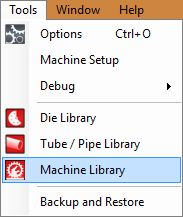
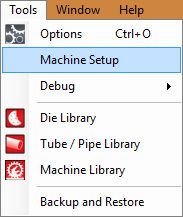
- After opening the Bend-Tech CAM software, choose either one of these steps to enter the machine calibration page.
1. Click directly on the Machine Library ![]() icon from the right hand side of the Task Menu screen and select the Wizard
icon from the right hand side of the Task Menu screen and select the Wizard  button.
2. Click on the Tools button from the Main Menu Bar, then the Machine Library ![]() icon and select the Wizard
icon and select the Wizard  button.
3. Click on the Tools button from the Main Menu Bar, then the Machine Setup button.
Dragon Calibration Wizard
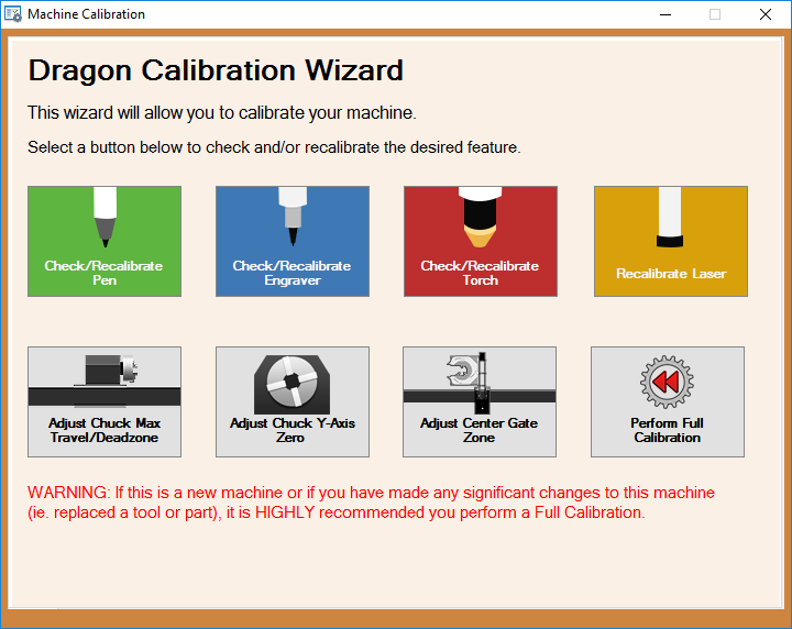
This initial startup screen for the Calibration Wizard will allow you to choose from multiple options for calibrating different aspects of your machine, or complete an overall calibration from the beginning.
Introduction
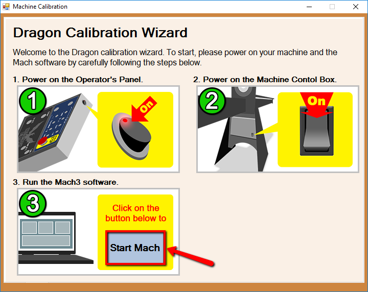
- This introduction gives you a small insight into the tasks that are expected during this calibration and instructs you to turn on the power on the control panel and on the Dragon machine.
- When the machine is turned on, click the "Start Mach" button to continue to the next page.
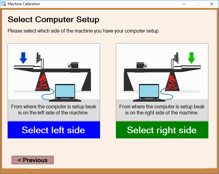
Select Computer Setup
- The "Select Computer Setup" page will open your Mach program and it will ask you which side of the Dragon machine your computer is located on.
- Select the image that describes your computer's location in reference to the Dragon machine to move on to the next page in the calibration.
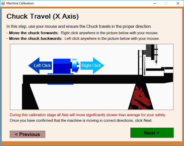
Chuck Travel (X Axis)
- This page will prompt you to adjust the chuck travel to ensure that it is moving in the proper direction when you press the left and right buttons on your mouse.
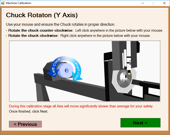
Chuck Rotation (Y Axis)
- This page will prompt you to adjust the chuck rotation to ensure that it is rotating in the proper direction when you press the left and right buttons on your mouse.
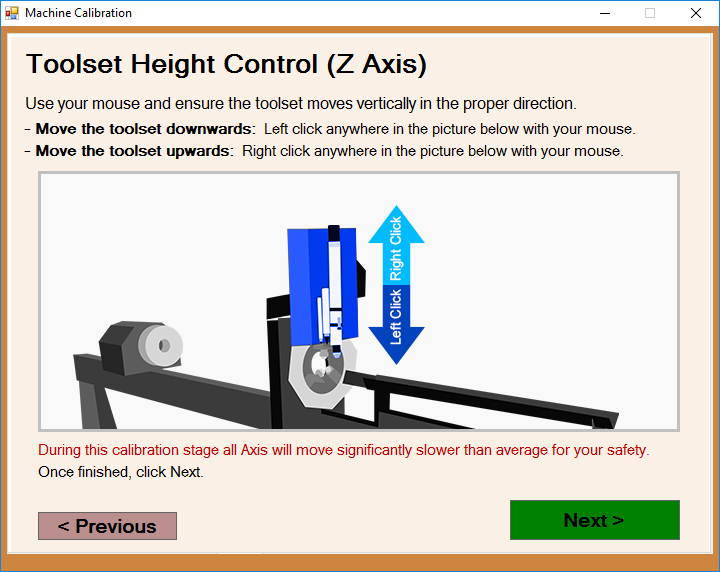
Toolset Height Control (Z Axis)
- This page will prompt you to adjust the tool height to ensure that the toolset is moving in the proper direction when you press the left and right buttons on your mouse.
A-Axis Movement: Tool Change
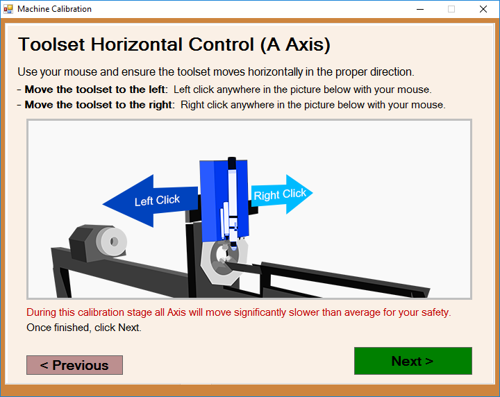
- This page will prompt you to adjust the toolset's horizontal movement to ensure that it is moving in the proper direction when you press the left and right buttons on your mouse.
Check Homing Switch (X Axis)
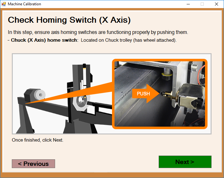
- The page will point to the manual switch for the X axis. You are prompted to press the X axis switch followed the Next button.
Check Homing Switch (A Axis)
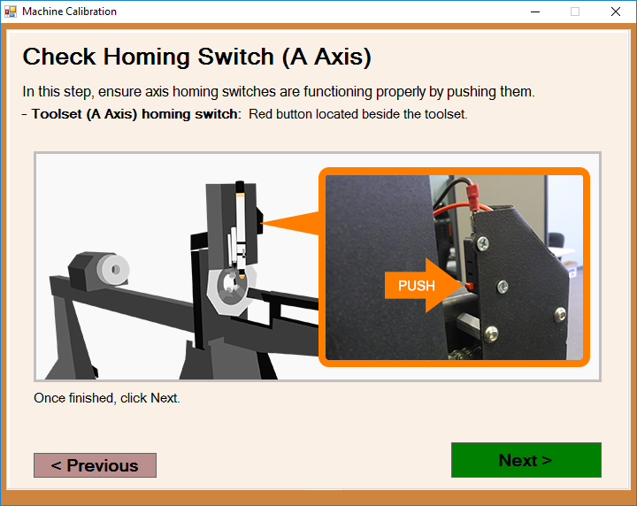
- The page will point to the manual switch for the A axis. You are prompted to press the A axis switch followed the Next button.
Rapid Travel
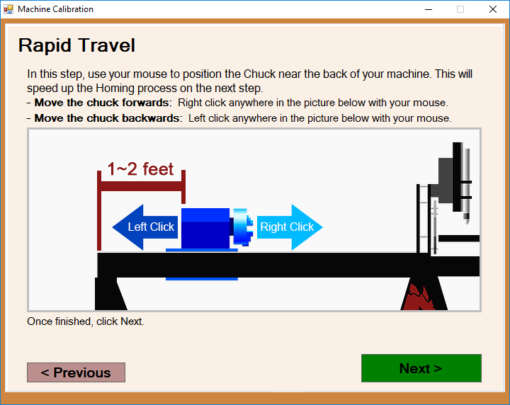
- This page will prompt you to move the chuck near the back of the machine using the left and right buttons on your mouse followed the Next button.
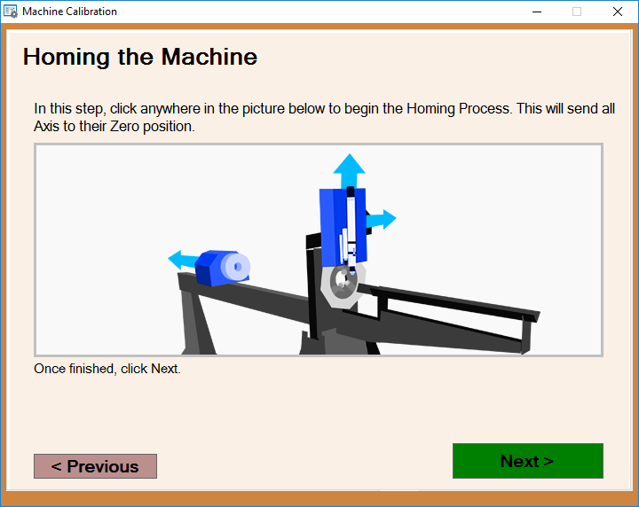
Homing the Machine
- This page will prompt you to click anywhere in the picture in order to send the machine to its home position.
- Then, click the next button.
For Square and Rectangle Machines Only
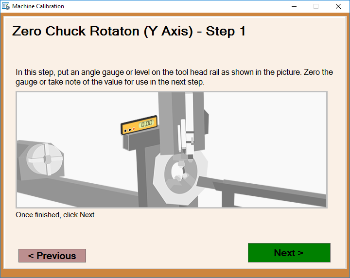
Zero Chuck Rotation (Y Axis) - Step 1
- This page will prompt you to place an angle gauge or level onto the tool head rail located directly behind the tool changer. Then, zero out the angle gauge or read the bubble location on your level and note the value for use in the next step.
- Then, click the next button.
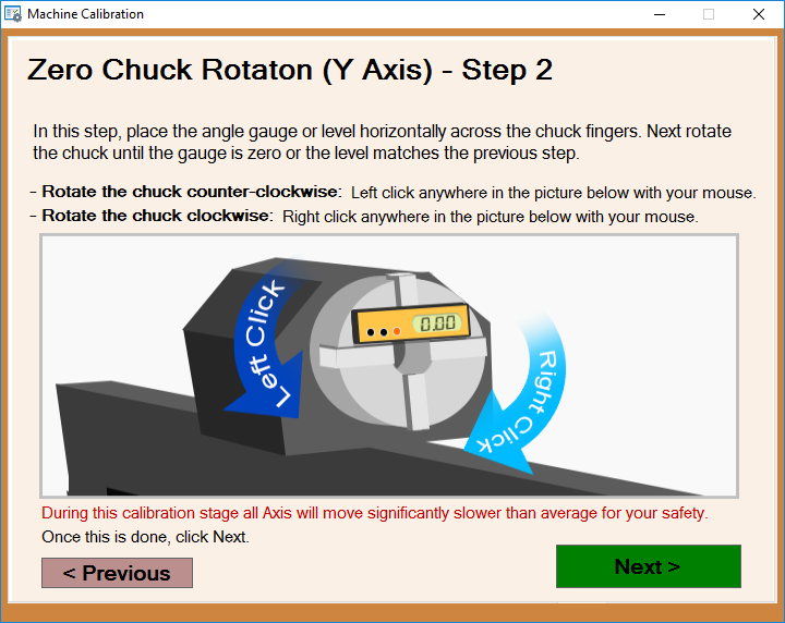
Zero Chuck Rotation (Y Axis) - Step 2
- This page will prompt you to place your angle gauge or level and place it on the fingers of the chuck. Then, rotate the chuck using the left and right click buttons on your mouse until the angle gauge or level reads as it did on the rail from the previous step.
- Then, click the next button.
For all 21' Dragon Machines
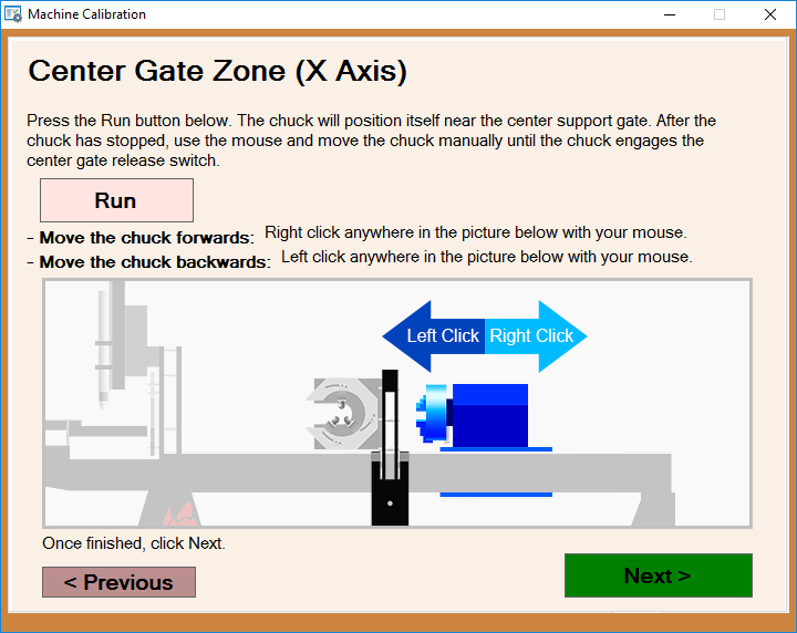
Center Gate Zone (X Axis)
- This page will prompt you to click the Run button so that the chuck positions itself directly behind the center support gate on your 21' Dragon machine.
- Then, clicking in the picture provided, use the left and right buttons on your mouse to move the chuck forward until it activates the center gate release switch.
- Then, click the next button.
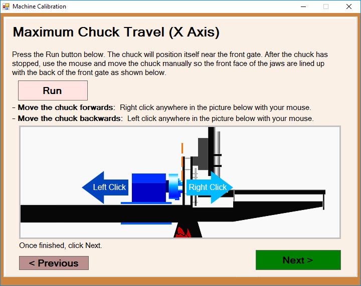
Maximum Chuck Travel (X Axis)
- This page will prompt you to click on the Run button on the screen in order to position the chuck near the front gate. Then, back the chuck off so that the jaws of the chuck are lined up with the rear face of the front gate.
- Then, click the next button.
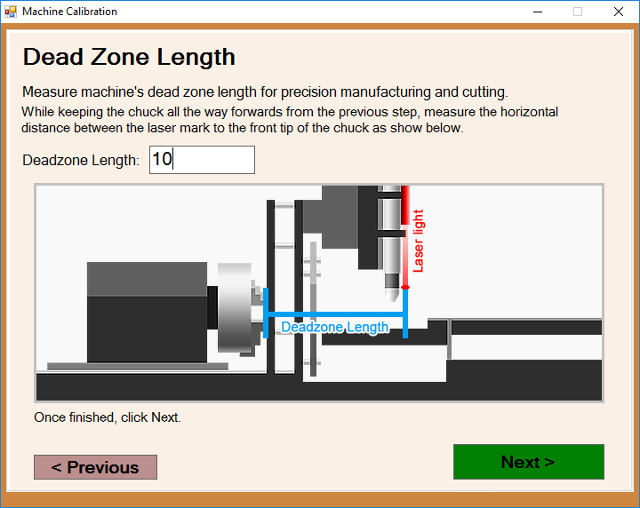
Dead Zone Length
- This page will prompt you to measure the length from the front jaws of the chuck to the laser light when the chuck is in its front most position.
- Enter the measured length in the Deadzone Length value field and select the next button when you're finished.
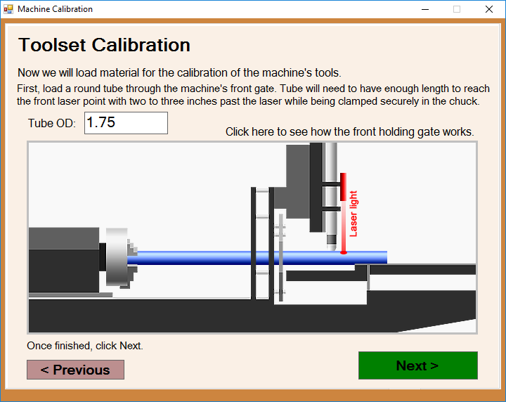
Toolset Calibration
- This page will prompt you to load the material used for this calibration, making sure to locate the end of the tubing a few inches past the laser positioning light.
- Enter the OD of the tubing into the Tube OD value field and click the next button to continue.
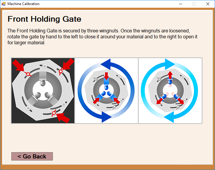
Front Holding Gate Operation
- Click the wording that reads Click here to see how the front holding gate works and a window will appear showing you how to adjust the front gate to accommodate your tubing OD.
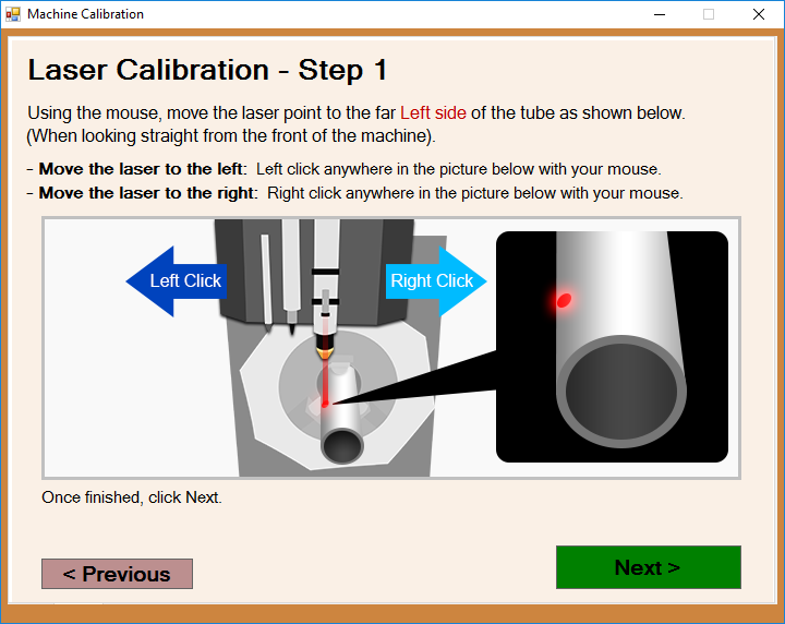
Laser Calibration - Step 1
- This page will prompt you to use the left and right buttons on your mouse to move the laser left and right until it touches the left most edge of the tubing.
- Next, press the next button to register the information with the software and continue.
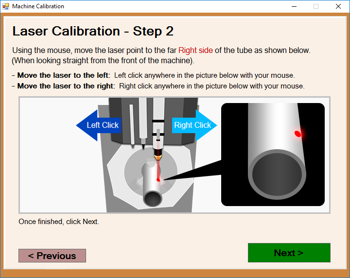
Laser Calibration - Step 2
- This page will prompt you to use the left and right buttons on your mouse to move the laser left and right until it touches the right most edge of the tubing.
- Next, press the next button to register the information with the software and continue.
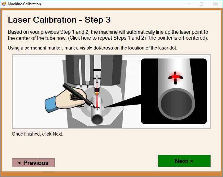
Laser Calibration - Step 3
- This page automatically use the information from the two previous steps and attempt to find the center of the tubing.
- If the location of the laser is not completely centered on the tube, repeat the previous steps to ensure an accurate calibration, then mark the absolute center with a marker.
- Then, click the next button to continue.
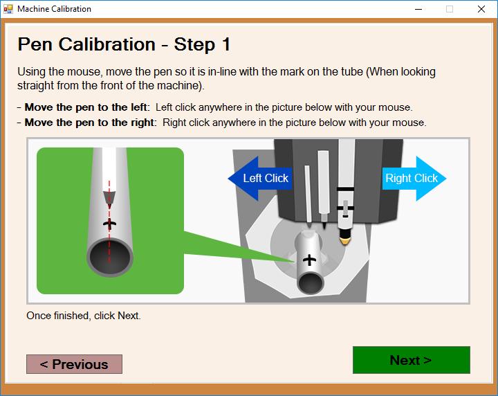
Pen Calibration - Step 1
- This page will prompt you to use the left and right buttons on your mouse to move the marker perpendicular to the length of the tubing (Z-Axis) until it lines up with the mark you've created on the center of the tubing. Then, press the next button to register the information with the software.
Pen Calibration - Step 2
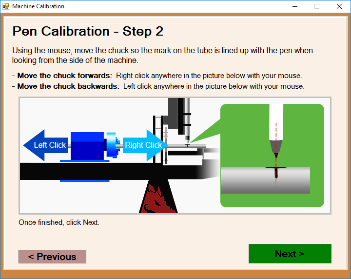
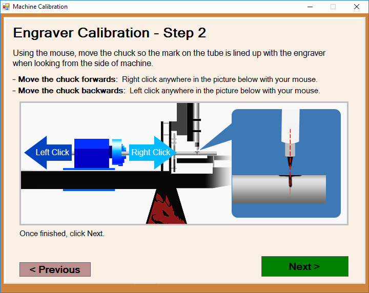
- This page will prompt you to use the left and right buttons on your mouse to move the marker along the length of the tubing (X-Axis) until it lines up with the mark in the center of the tubing. Then, press the next button to register the information with the software.
Pen Calibration - Step 3
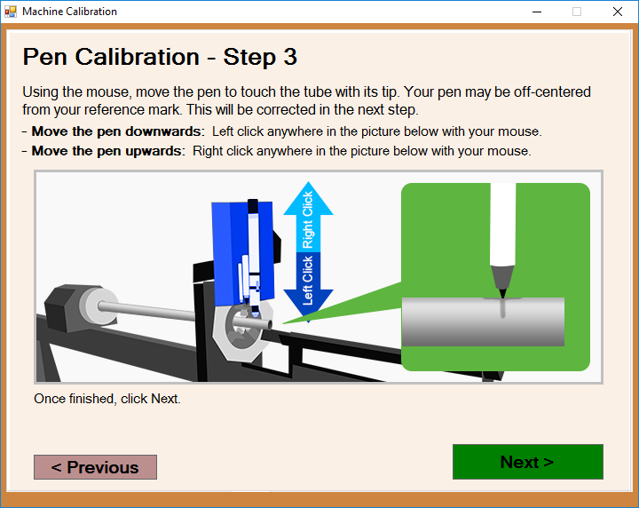
- This page will prompt you to use the left and right buttons on your mouse to move the marker vertically (X-Axis) to meet with the mark in the center of the tubing. Then, press the next button to register the information with the software.
Adjust Pen
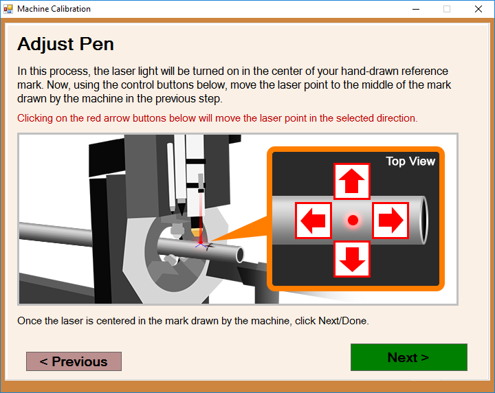
- This page will prompt you to use the red arrow buttons to move the laser left, right, forward and backward to find the center of the mark on the tubing.
- Then, press the next button to register the information with the software.
Engraver Calibration - Step 1
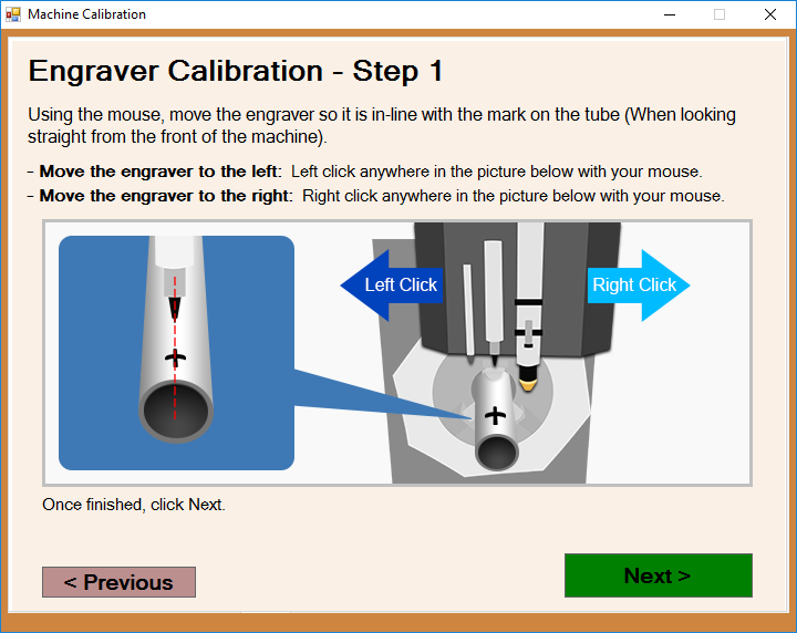
- This page will prompt you to use the left and right buttons on your mouse to move the engraver perpendicular to the length of the tubing (Z-Axis) until it lines up with the mark you've created on the center of the tubing. Then, press the next button to register the information with the software.
Engraver Calibration - Step 2
- This page will prompt you to use the left and right buttons on your mouse to move the engraver along the length of the tubing (X-Axis) until it lines up with the mark in the center of the tubing. Then, press the next button to register the information with the software.
Engraver Calibration - Step 3
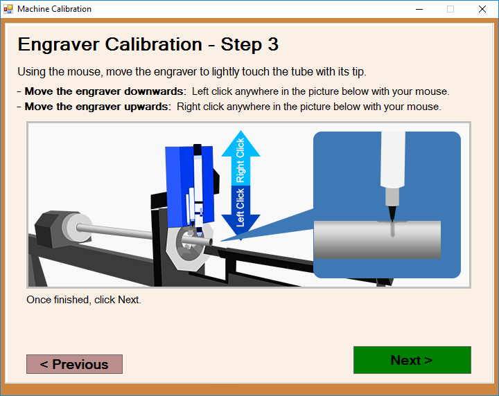
- This page will prompt you to use the left and right buttons on your mouse to move the engraver vertically (X-Axis) to meet with the mark in the center of the tubing. Then, press the next button to register the information with the software.
Adjust Engraver
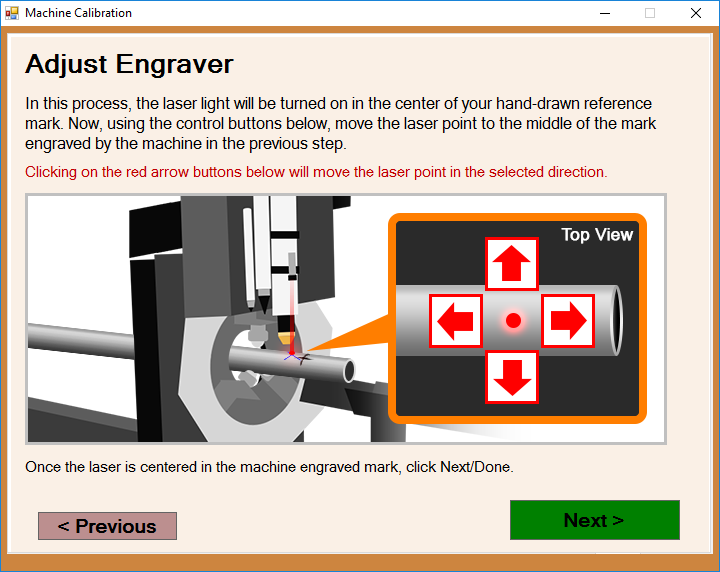
- This page will prompt you to use the red arrow buttons to move the laser left, right, forward and backward to find the center of the mark on the tubing.
- Then, press the next button to register the information with the software.
Torch Calibration - Step 1
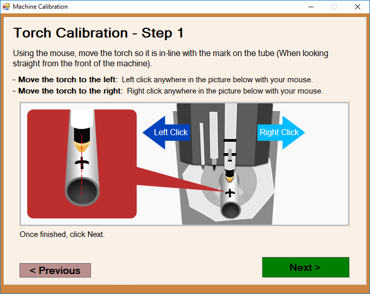
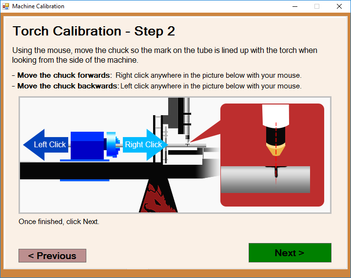
- This page will prompt you to use the left and right buttons on your mouse to move the torch perpendicular to the length of the tubing (Z-Axis) until it lines up with the mark you've created on the center of the tubing. Then, press the next button to register the information with the software.
Torch Calibration - Step 2
- This page will prompt you to use the left and right buttons on your mouse to move the torch along the length of the tubing (X-Axis) until it lines up with the mark in the center of the tubing. Then, press the next button to register the information with the software.
Torch Calibration - Step 3
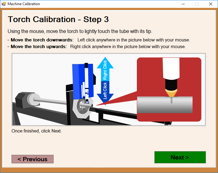
- This page will prompt you to use the left and right buttons on your mouse to move the torch vertically (X-Axis) to meet with the mark in the center of the tubing. Then, press the next button to register the information with the software.
Adjust Torch
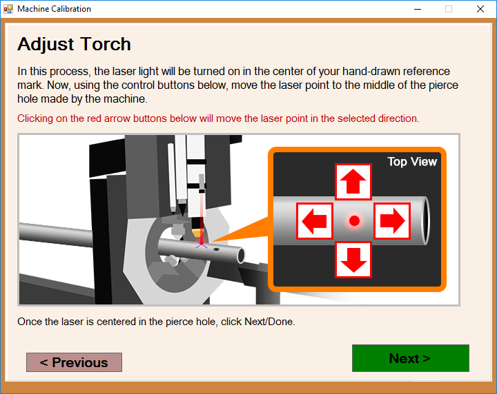
- This page will prompt you to use the red arrow buttons to move the laser left, right, forward and backward to find the center of the mark on the tubing.
- Then, press the next button to register the information with the software.
Toolset Verification
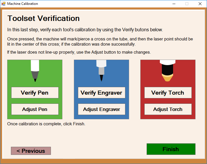
- This last window will prompt you to move each of the tools on the toolset to validate their position and see if you need to make adjustments to any of them.
- When you're sure that the tools have all been calibrated correctly, click the finish button to lock in the information and close the calibration wizard.
