Difference between revisions of "Cutting Tutorial"
| Line 106: | Line 106: | ||
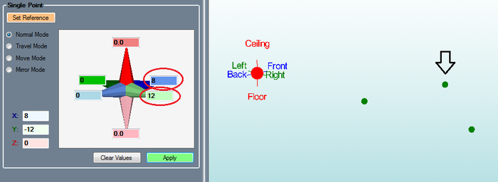
| − | Leave '''12''' in the '''Right''' field and enter '''8''' in the '''Front''' field. | + | Leave '''12''' in the light green '''Right''' field and enter '''8''' in the darker blue '''Front''' field. |
| Line 131: | Line 131: | ||
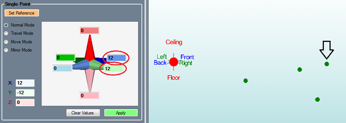
| − | Enter '''12''' in the '''Front''' field, '''12'''' in the '''Right''' field, then click '''Apply'''. | + | Enter '''12''' in the darker blue '''Front''' field, '''12'''' in the light green '''Right''' field, then click '''Apply'''. |
Revision as of 13:49, 13 June 2014
In this tutorial you will learn how to add cuts to tubes in an assembly project.
Note: Inches are used as the measurement units throughout this tutorial.
Step 1
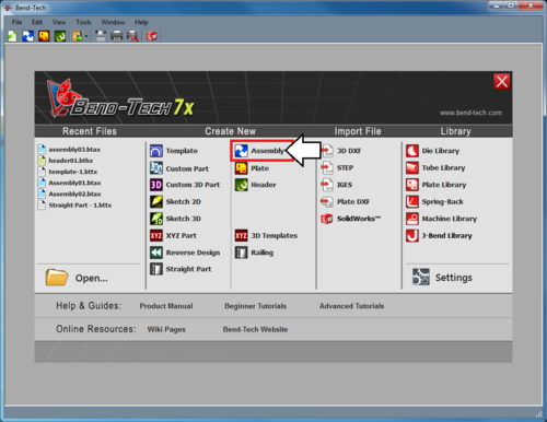
Start by launching the Bend-Tech 7x software and opening a new assembly design. This can be done by:
1.) Go to the File menu, select New Assembly.
2.) Click the New Assembly icon ![]() at the top of the window.
at the top of the window.
...OR
3.) Select the Assembly option from the Task Menu that appears when the software starts up.
Step 2
Before we start, we need to put a few parts together so that we have something to cut.
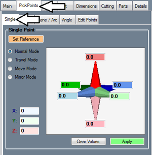
Go to the PickPoints tab and the Single sub-tab.
Step 3
Click the Set Reference button ![]() and click the point at the center of the Tri-Star (this should be the only point on the screen right now). If you successfully select the point, it will turn red.
and click the point at the center of the Tri-Star (this should be the only point on the screen right now). If you successfully select the point, it will turn red.
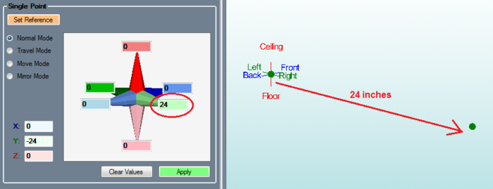
Enter 24 in the light green Right field, then click the Apply button. ![]()
Step 4
Click the Clear Values button.
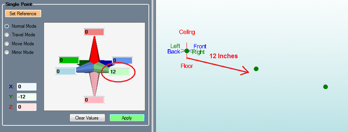
Enter 12 in the light green Right field and click Apply.
Step 5
Leave 12 in the light green Right field and enter 8 in the darker blue Front field.
Click the Apply button.
Step 6
Click the Clear Values button.
Enter 12 in the darker blue Front field, 12' in the light green Right field, then click Apply.
Step 7
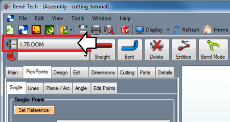
Select a material in the upper left corner of the assembly window. (Note: If there are no materials available, one will need to be created. Refer to the Tube/Pipe Library page for information on how to define tube materials.)
Step 8
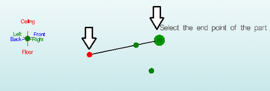
Click the Straight Part button.
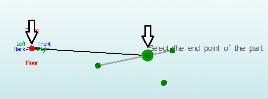
Connect the two points that are indicated in the picture below.
Step 9
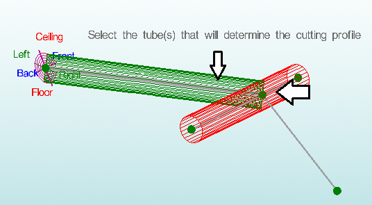
Connect the two points that are indicated in the picture below.
Step 10
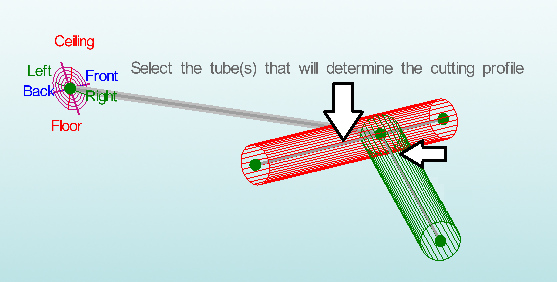
Connect the two points that are indicated in the picture below.
You are now finished building the part.
Step 11
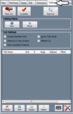
Go to the Cutting tab.
Step 12
Next, click on the Left tube. This will be the tube that is cut. Now, click on the middle tube. This tube will define how the first tube is cut.
Step 13
The cut will then be added to the cut list.
Zoom in on the part model to see a better view of the cut outline. The cutting profile will be represented by the blue and black lines.
Step 14
Click the New Cut button ![]() again.
again.
Click the right tube, followed by the middle tube to define a second cut.
Step 15
The second cut will then be added to the cut list.
Again, zoom in on the part model to see a better view of the cut outline. The cutting profile will be represented by the blue and black lines.
Step 16
You are now finished adding cuts to the part.
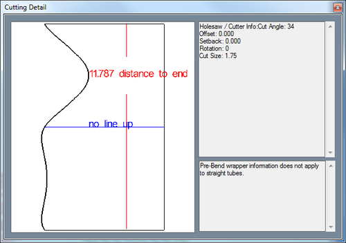
To see a preview of the cutting wrapper (shown to the right), click the Details ![]() below the cut list.
below the cut list.
If you wanted to print out cutting sleeves for both cuts, you could do so by clicking the Print All button ![]() below the cut list.
below the cut list.
