Machine Library
Bend-Tech 7x Wiki :: Main Menu Bar :: Tools :: Machine Library
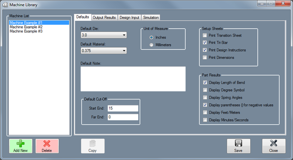
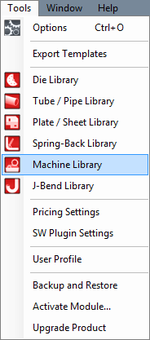
To access the machine library, click on the Tools menu and select the Tube Library option in the drop down menu or click on the Tube Library option on the task menu.
Defaults
Default Die
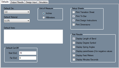
The die shown here will be the default die used for this machine. To choose a default die, click on the drop down menu and select a die from the list. The dies shown here are created in the Die Library.
Default Material
The tube material shown here will be the default material used for this machine. To choose a default material, click on the drop down menu and select a die from the list. The dies shown here are created in the Tube/Pipe Library.
Unit of Measure
The unit of measure the the machine uses can be specified here. Machine units can be either inches or millimeters.
Default Note
The notes supplied here will the be default notes attached to this machine. To add notes, type in the provided text field.
Default Cut-Off
These cut-off values are the default amount of extra material needed on either end of the part when bending tubes with this machine. To add cut-off values, enter values into either of these fields.
Setup Sheets
- Print Transition Sheet: The transition sheet will include a chart that displays the location, rotation, and bend angle values for each bend on the part. Each location, rotation, and angle will have a image of the 3D part showing what the part will look like at that specific stage. By default, these instructions will be included on the print out while this option is checked.
- Print Tri-Star: By default, the part model will have the tri-star included on the print out while this option is checked.
- Print Design Instructions: By default, the design instructions chart will be included on the print out while this option is checked.
- Print Dimensions: By default, the part model will have the dimension markers and values included while this option is checked.
Part Results
- Display Length of Bend: Check this box to have length of bend values included in the results table.
- Display Degree Symbol: Check this box for angle values to have degree symbols shown next to them in the results table.
- Display Spring Angles: Check this box for spring angle values to be included in the results table.
- Display parentheses () for negative values: Check this box to have all negative values enclosed in parentheses in the results table.
- Display Feet/Meters: Check this box for large length values to be displayed in terms of feet or meters (feet will be used if inches are used as the units and meters will be used if millimeters are the units.)
- Display Minutes/Seconds: Check this box for angle values to be displayed in terms of minutes and seconds instead of decimal degree values.


