Machine Library
Bend-Tech 7x Wiki :: Main Menu Bar :: Tools :: Machine Library
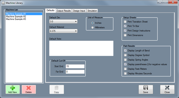
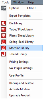
To access the machine library, click on the Tools menu and select the Machine Library option in the drop down menu or click on the Machine Library option on the task menu.
Defaults
Default Die
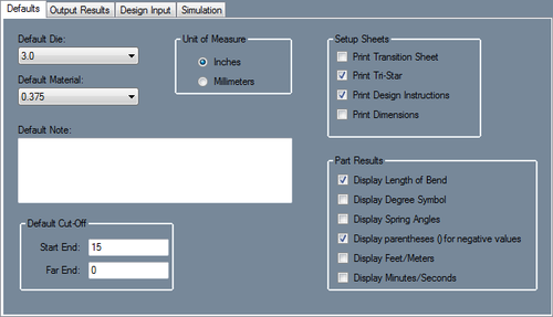
The die shown here will be the default die used for this machine. To choose a default die, click on the drop down menu and select a die from the list. The dies shown here are created in the Die Library.
Default Material
The tube material shown here will be the default material used for this machine. To choose a default material, click on the drop down menu and select a die from the list. The dies shown here are created in the Tube/Pipe Library.
Unit of Measure
The unit of measure the the machine uses can be specified here. Machine units can be either inches or millimeters.
Default Note
The notes supplied here will the be default notes attached to this machine. To add notes, type in the provided text field.
Default Cut-Off
These cut-off values are the default amount of extra material needed on either end of the part when bending tubes with this machine. To add cut-off values, enter values into either of these fields.
Setup Sheets
- Print Transition Sheet: The transition sheet will include a chart that displays the location, rotation, and bend angle values for each bend on the part. Each location, rotation, and angle will have a image of the 3D part showing what the part will look like at that specific stage. By default, these instructions will be included on the print out while this option is checked.
- Print Tri-Star: By default, the part model will have the tri-star included on the print out while this option is checked.
- Print Design Instructions: By default, the design instructions chart will be included on the print out while this option is checked.
- Print Dimensions: By default, the part model will have the dimension markers and values included while this option is checked.
Part Results
- Display Length of Bend: Check this box to have length of bend values included in the results table.
- Display Degree Symbol: Check this box for angle values to have degree symbols shown next to them in the results table.
- Display Spring Angles: Check this box for spring angle values to be included in the results table.
- Display parentheses () for negative values: Check this box to have all negative values enclosed in parentheses in the results table.
- Display Feet/Meters: Check this box for large length values to be displayed in terms of feet or meters (feet will be used if inches are used as the units and meters will be used if millimeters are the units.)
- Display Minutes/Seconds: Check this box for angle values to be displayed in terms of minutes and seconds instead of decimal degree values.
Output Results
Rotation
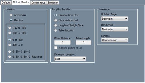
These rotation settings will control how the rotation values are displayed in the results table for this machine.
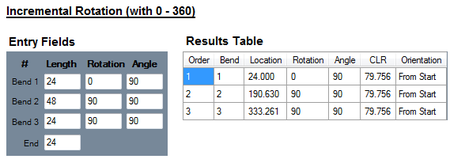
- Incremental: Rotation angles will start from the end of the previous bend's rotation. Click the incremental rotation option to select it.
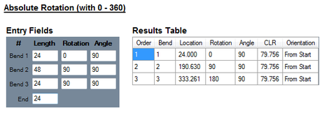
- Absolute: Rotation angles will always start from the very beginning of the angle scale. Click the absolute rotation option to select it.
- Angle Scale: The rotation scale will determine what the rotation angles will range between. The rotation scale will show where the angle measurements begin and where they end. Choose a rotation scale by clicking on one of the scale options. The rotation scales available are 0 - 360, 360 - 0, (-180) - 180, and 180 - (-180). The 0 - 90 - 0 - 90 - 0 and 0 - 90 - 0 - 90 - 0 Reversed options will be added when the Absolute option is chosen.
Length/Location
The length/location setting will determine how the bend location will be calculated in the results table with this machine.
- Distance from Start: Bend locations will be measured from the starting edge of the tube.
- Distance from End: Bend locations will be measured from the ending edge of the tube.
- Length of Straight Tube: Bend location values will be the amount of straight tube between each bend.
- Table Location: Bend locations will be based on index table values. If this option is used, the offset distance between the table and the bend will need to be supplied as well as scale length of the table. Check the Indexing Begins at Die option if the scale begins at the die.
- Dimension Location: This option determines where the bend location marks will be placed in reference to the bend. Bend locations can be placed at the start, center, or end of each bend.
Tolerance
The decimal tolerance for the lengths, angles, and rotations of the machine can be adjusted here. The decimal tolerance controls how many digits will be allowed after decimals points for length, angle, and rotation. In the tolerance options, each digit place is represented by an n.
For example, if the angle tolerance is set to n.nn and the actual angle is 90.539°, the angle will be rounded to 90.54°. If the angle tolerance is set to just n, then the angle would be rounded to 91°.
- Rotation Angle: To change the decimal tolerance for part rotation values, click the drop down menu and select a tolerance option from the list.
- Bend Angle: To change the decimal tolerance for bend angle values, click the drop down menu and select a tolerance option from the list.
- Lengths: Length values can be displayed in either fractional or decimal format. To change the format and/or tolerance for lengths, click the drop down menu and select an option from the list.
Design Input
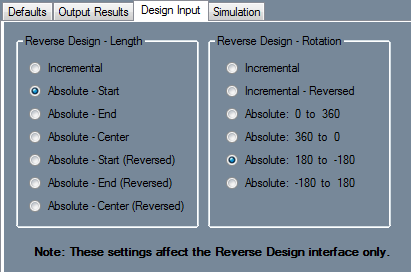
Reverse Design - Length
This setting will determine how inputted part lengths are interpreted when creating a reverse design part while using this machine.
- Incremental: Entered length values start from the previous bend.
- Absolute - Start: Entered length values are the distance from the starting edge of the tube to the starting edge of each bend.
- Absolute - End: Entered length values are the distance from the ending edge of the tube to the ending edge of each bend.
- Absolute - Center: Entered length values are the distance from the starting edge of the tube to the center of each bend.
- Absolute - Start(Reversed): Entered length values are the distance from the end of the part to the start of each bend.
- Absolute - End(Reversed): Entered length values are the distance from the end of the part to the end of each bend.
- Absolute - Center (Reversed): Entered length values are the distance from the end of the part to the center of each bend.
Reverse Design - Rotation
This setting will determine how rotations will be calculated in the results table when creating a reverse design part while using this machine.
- Incremental: Entered rotation values start from the end of the previous rotation.
- Incremental - Reversed: Entered rotation values start from the end of the previous rotation with a reversed direction.
- Absolute: 0 to 360: Entered rotation values always start from the beginning of the angle scale (0) at each rotation.
- Absolute: 360 to 0: Entered rotation values always start from the beginning of the angle scale (360) at each rotation.
- Absolute: 180 to -180: Entered rotation values always start from the beginning of the angle scale (180) at each rotation.
- Absolute: -180 to 180: Entered rotation values always start from the beginning of the angle scale (-180) at each rotation.
Simulation
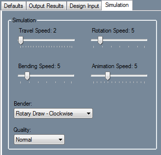
In the Simulation tab, the default travel, bend, rotation, and animation speed, as well as the default bender type, simulation quality and POB bracket color can be set. These settings are only defaults and can be adjusted while viewing the simulation.
Speeds
The default speeds of the travel, bending, rotation, and animation can be adjusted independently. To adjust the speeds, click and drag the point back and forth.
Bender
The bender chosen here will determine the type of bender used in simulation. The bender options available are: center compression, rotary compression - clockwise, rotary compression - counter clockwise, rotary compression - vertical, rotary draw - clockwise, rotary draw - counter clockwise, and rotary draw - vertical.
Quality
The display quality of the simulation animation can be adjusted here. To adjust the simulation, click on the drop down menu and choose a quality option.
