STEP/IGES Import
Bend-Tech 7x Wiki :: Main Menu Bar :: File :: Import :: STEP/IGES Import
Video Link
- The video link here will show the absolute basics of the importing process. If your experience adds more complications, please read this page for a better understanding on the importing process.
Importing a File
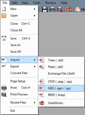
To import a file of one of these types, place the cursor on the "Import" option in the "File" menu and select an option from the menu. Choose a file to import in the Import (File Type) File window. Click "Open" to open it into an Import Part window.
The main steps to follow when defining and importing a part are:
1.) Choose a material in the "Die and Material" tab.
2.) Define the desired part sections using the tools in the "Define" tab.
3.) Set the starting section of the part.
4.) As an option, choose a die for each bend on the part.
5.) Transfer the part to a single part designer, assembly, etc. using the "Transfer" menu. ![]()
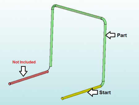
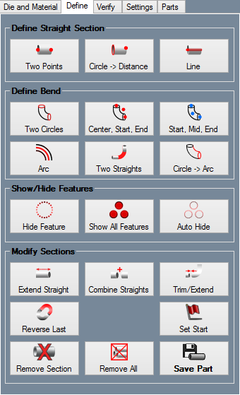
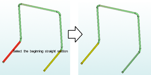
- Once each bent and straight section of the part is defined (the red tubes) using the definition tools, the starting straight length of the part will need to be defined.
- Once the start length is chosen, the part will be tracked according to the chosen sections. All sections that are connected to the starting length/together will be included in the final imported part. The final part will be colored green. See below for an example.
Die and Material
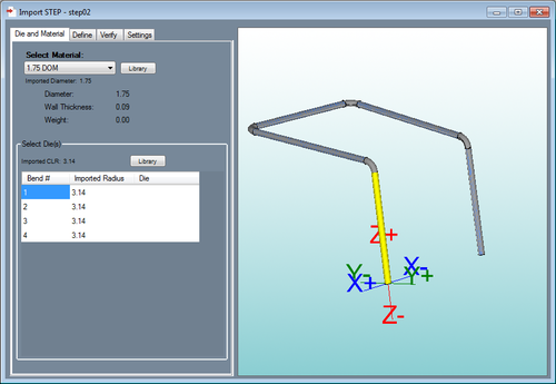
- In the Die and Material tab, a material and die can be selected. The material selection will be shown in the 3D display of the imported part when the 'Preview Part' button is clicked.
Select Material
- To select a material, click the drop down menu below "Select Material" and choose a material from the list. Once a material is selected, the diameter, wall thickness, and weight of the selected material will be shown to the right. Directly below the Select Material drop down menu, the original diameter of the imported part will be shown after 'Imported Diameter'. To view the material library, select the "Library" button next to the material selection. A material must be selected before a 3D shaded model of the part can be shown in the part display frame.
Select Die(s)
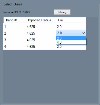
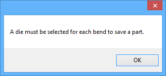
- Once the part has be properly defined, each bend can have a die assigned to it. Click the drop down menu below the Die column and choose a die from the list. Above the bend chart, the original CLR of the imported part will be shown after "Imported CLR". To view the die library, click the "Library" button next to the die selection.
Define
- Before a part can be fully imported, each section that needs to be included on the part must be defined.
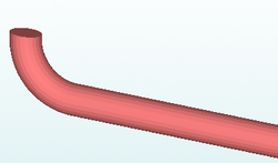
- Before beginning, keep in mind that a section is represented by a lighter red shade as seen below. This does not represent the part that will be imported. This only defines which sections can be included in the part definition. When single parts are first brought into the import interface, the part sections may already be defined.
- Also, sections are defined based off the centerline. So, for example, if the Two Points tool is used to define a section, the line between those two points will be used to represent the centerline of that section.
Define Straight Section
Two Points
- To define a section using two points, select the "Two Points"
 button. First, click on one pick point. Once the first point is selected, a green wireframe preview of the section will generate from this point. To place the end of this section, select another Pickpoint.
Circle -> Distance
- To define a section by selecting a circle and any point, select the "Circle -> Distance"
 button. First, select on a circle feature. Once the circle is selected, a green wireframe preview of the section will generate from this point. Next, define the length of the section by choosing a Pickpoint.
Line
- To define a section by selecting a line feature, select the "Line"
 button. Next, click on a line feature that will represent the centerline of the section.
Define Bend
Two Circles
- To define a bend between two circle features, click the Two Circles
 button. Next, click on the first circle. Once the circle is selected, a green wireframe preview of the section will generate from this point. Then click on another circle to place the section.
Center, Start, End
- To define a bend by selecting the center, start, and end points, select the Center, Start, End
 button. Next, click the centerpoint of the bend. This point will be located off the bend, at the center of the arc as if it were a full circle. Then click on the starting point of the arc and lastly, the end point of the arc to place the section.
Start, Mid, End
- To define a bend by defining the starting point, mid point, and end point, select the Start, Mid, End
 button. First, selecting the centerline start point of the arc, the mid point, and then the centerline end point.
Arc
- To define a bend by selecting an arc feature, select the "Arc"
 button. Next, select on an arc feature that will represent the centerline of the bend.
Two Straights
- To define a bend by selecting the straight lengths on either side, select the "Two Straights"
 button. Click on the line on one side of the arc, then click on the line on the other side.
Circle -> Arc
- To define a bend with only a circle and an arc, select the "Circle -> Arc"
 button. Click on the circle representing the tangent of the bend, then click the line indicating the arc of the bend.
Show/Hide Features
Hide Feature
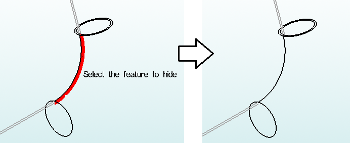
- To hide a single line, arc, or circle feature, first select the "Hide Feature"
 button. Then, click directly on the feature.
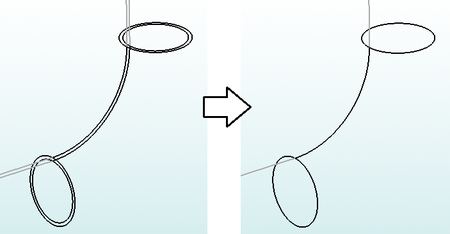
Show All Features
Auto Hide
Modify Sections
Extend Straight
- To add or remove length from a straight section of tube, select the "Extend Straight"
 button. Next, click on the section that will be adjusted. Then enter the amount to add or remove (enter as a negative to shorten) and select the "OK" button.
Combine Straights
- To fuse two straight sections together, select the "Combine Straights"
 button. Next, click on the first straight, then the second straight lengths that will be combined.
Trim/Extend
- To trim or extend a straight section in order for it to line up with a bent section, select the "Trim/Extend"
 button. First, click the straight section that will be adjusted. Next, click on the bent section that the section will line up to.
Reverse Last
Set Start
- To set the starting section of the part, select the "Set Start"
 button. This section will define where the part begins and must be a straight length, bends cannot be used as the starting length. After clicking the button, simply select a section of tube to set it as the start. Once selected, the start section will turn yellow.
(Note) Once the start is chosen, the part will be tracked. The tracked sections that will be included in the imported part will be shaded green.
Remove Section
- To remove a defined section from the part, select the "Remove Section"
 button. Then, just click on a light red section for it to be removed.
Remove All
Save Part
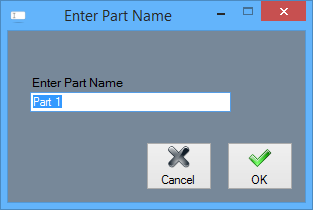
- When the part is completely defined using manual tools, select the "Save Part"
 button and you will be prompted to give the saved part a name.
Verify
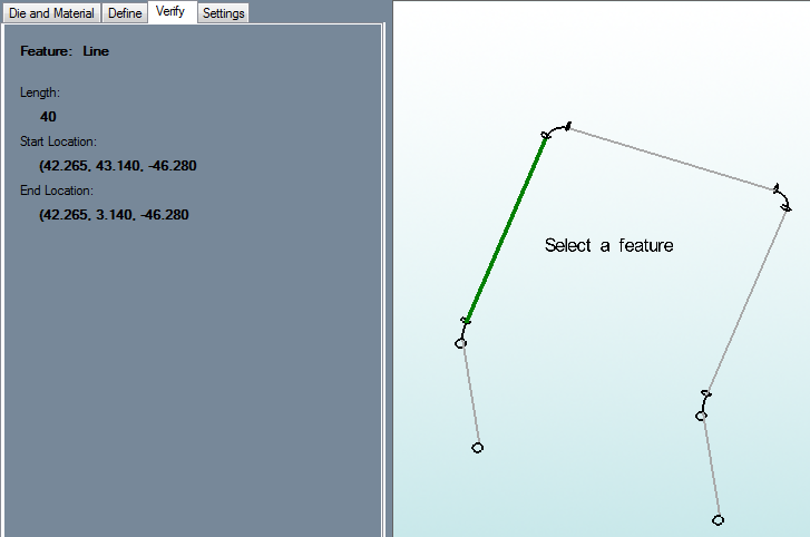
- Under the Verify tab, the selected feature's attributes will be shown.
- Click on a feature to select it. If the selected feature is a line, the length, start and end points will be shown. If the selected feature is an arc, the radius, angle, center, start, and end locations will be shown.
Settings
Import References
Die References
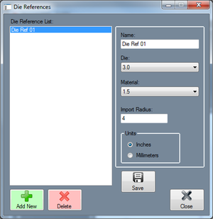
- Die references can be set up by clicking the Die button
 in the Import References section. This will open the Die References window. The purpose of die references is to automatically assign a die to any bends in a part that have the same material and import radius as the reference. For example, if an imported part is brought into the import interface and is assigned a material that matches the material reference (Under Die and Material in the top right corner) and has the same import radius as the die reference, once "Generate Part" is selected, the die reference die will be automatically chosen as the die in the "Part Details" chart. On the left side of the die references window, there is a list of die references. To view information about a die reference, select it by clicking its name in the list. The fields to the right will display the selected die reference's details. To add a new die reference, select the "New" button at the bottom of the window. Enter the die reference's name in the "Name" field, select a die from the Die drop down menu, select a material from the 'Material' drop down menu, enter an import radius, and select which units to use. Select the "Apply" button to add it to the list. To delete a die reference, select the die reference from the list and click the 'Delete' button. Select "Close" to close the Die References window.
Material References
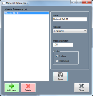
- Material references can be set up by clicking the Material button
 below "Import References". This will open the Material References window. The purpose of a material reference is to automatically select a material for a part if it has the same import diameter of the material reference. For example, if an imported part has a 2 inch diameter and a material reference's assigned import diameter is 2 inches, the material reference material will be automatically selected (Under Die and Material in the top right corner) once the part is brought into the import interface. A list of all material references will be shown on the left side of the window. To view information about a material reference, select it by clicking its name in the list. The fields to the right will display the selected material reference's details. To add a new material reference, click the "New" button at the bottom of the window. Enter the material reference's name in the "Name" field, select a material from the Material drop down menu, enter a import diameter in the "Import Diameter" field, and select which units to use. Select the "Apply" button to add it to the list. To delete a material reference, select the material reference from the list and click the "Delete" button. Select "Close" to close the Material References window.
Display Options
Display TriStar
- The axis will be shown on the graphical display.
Display Features
- The outline lines for the arcs and straight lengths will be displayed on the part model.
Display Sections
- The defined, lighter red sections of tube will be shown on part model.
Display Part
- Once the part is defined, the part will be shown in the selected material.
PickPoint Size:
- Use the PickPoint size drop down menu to change the size of all PickPoints in the Import part display.
Adjust Model Scale:
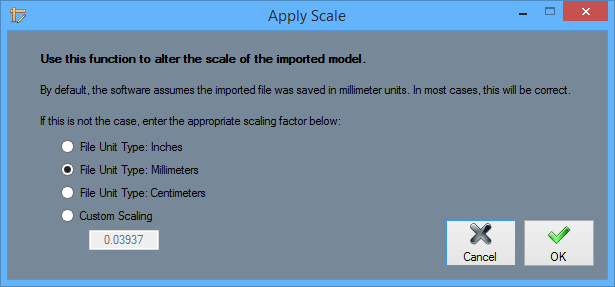
- Click the Scale button to change the scale of the imported model to either inches, millimeters, centimeters or a custom scale size.
Parts
- The part names will be listed here along with their respective material and die information.
Select All
- This will select all of the parts in the parts list. They can then all be transferred to an Assembly if directed by the user.
Select None
- This will deselect all of the parts in the parts list.
Delete Part
- This will delete the selected part(s) from the parts list and will remove their definition in the display screen to the right.
