Armor Pack Templates
Bend-Tech 7x Wiki :: Armor Pack Templates
Due to its length, the Armor Pack Templates Guide has a Table of Contents to accommodate the user.
Contents
Things to Know
The Armor Pack Templates options allow for a variety of Tube/Pipe created parts to be designed at the user's specific dimensions. Parts created in the Armor Pack Templates designer can be brought into Assembly and other select interfaces. Parts can also be cut and the wrappers for these cuts can be printed out after being sent to Single Part interfaces.
To open a new Armor Pack Template design:
- Select the "AP Templates"
 option from the Task Menu that appears when the software starts up, when all designs are closed, or through the view menu.
- When opening a new template window, it is easier if the user selects the "Maximize"
 button right away. This way, the part chosen by the user will appear in the center of the display area and will not be obstructed by the template's illustration in the upper left hand corner of the screen.
- Newly created template designs will be added to the existing list as they are developed. New templates will appear with regular updates.
Template Categories
Style of Cage
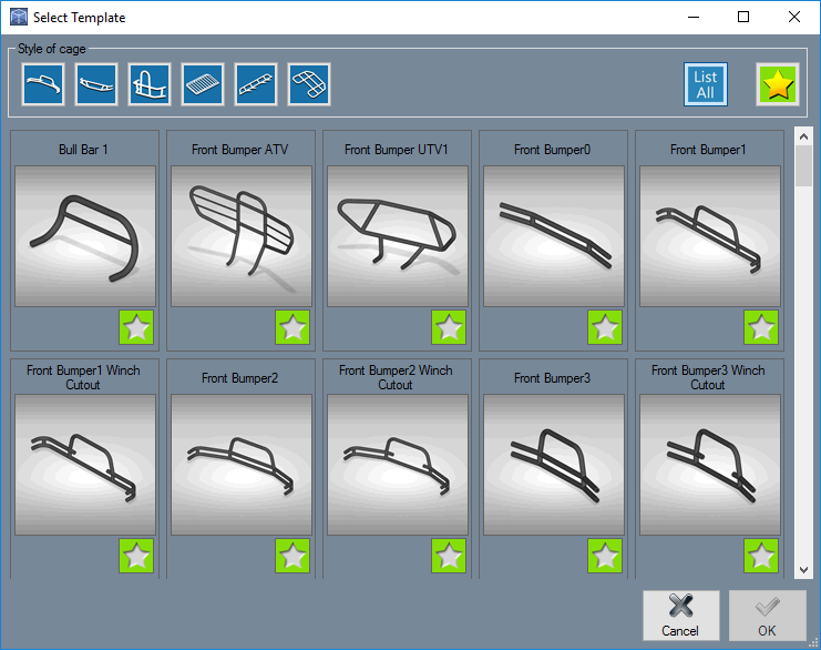
- The "Style of Cage" section shows all of the categories of Armor Pack Templates available.
- Selecting a style from the list will open a new page showing variations of template options for the user to open and adjust to their desired dimensions.
List All 
- The "List All" button will show every Armor Pack Template available.
Star 'Favorite' Button 
- The Star, or 'favorite' button will show all the templates that the user has saved to their favorites.
- Clicking the star will change it from white to gold, which indicates a user favorite. All gold starred templates are user favorites.
Template Tabs
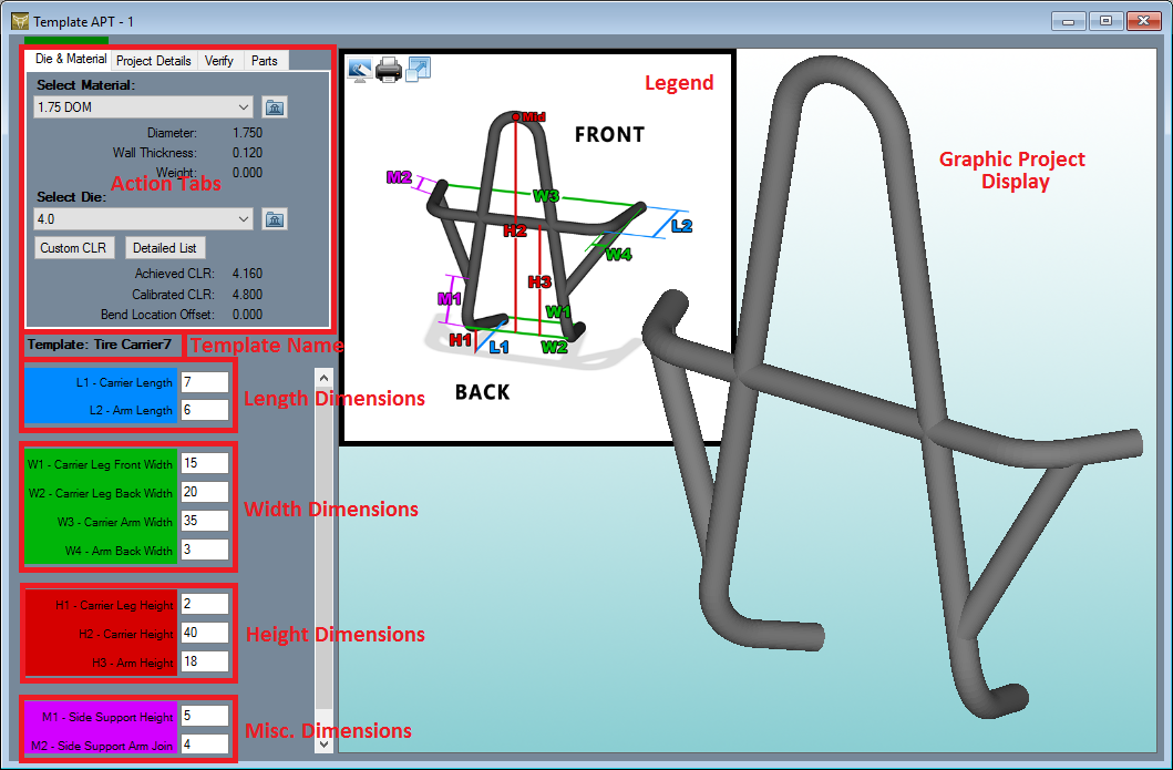
- Every template has four tabs. These tabs will always have the same buttons and entry fields. The only distinction between the templates is the "Current Template Values" section below, what the dimensions there represent, and the Parts tab along with the labeled parts contained in the project.
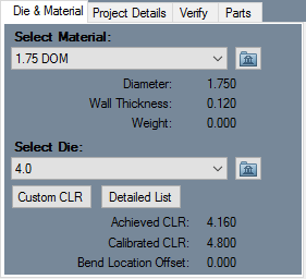
Die & Material:
- From here, users can choose the Material being used for the design, specify the Die that will be used, and assign a Custom CLR (SE only) to the part displayed to the right.
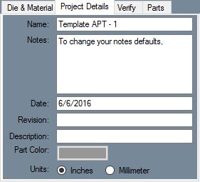
Project Details
- "Name:" is where the user can name the project.
- "Notes:" is where the user can make notes about the part's dimensions or specifications.
- "Date:" is where the user can mark when the part was created or when it is set to be manufactured.
- "Revision:" is where the user can update the date when the part specifications were revised.
- "Description:" is where the user can provide a description of the part's specifications.
- "Part Color:" is where the user can change the color of the tubing that will be seen in the project.
- "Units:" is where the user can change the length increments by selecting either the "Inches" or "Millimeters" options.
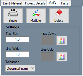
Verify
- Single: Click the Single
 button followed by a straight length of tubing in the design to place a dimension. You can also click on two pickpoints in the design to get the single length between the points and place the dimension.
- Multiple: Click the Multiple
 button to place multiple dimensions along a specified area of a project. First, select a pickpoint where the dimensions will start, then select an end point to place the dimensions. Between these features, each possible dimension will be placed.
Settings
The appearance of dimension text and markers can be adjusted using these settings.
- Text Size: The size of the dimension text can be supplied here. Larger values will result in larger dimension font size and vice versa.
- Text Color: The color of the dimension text can be chosen here. Click the color button and select a color to adjust text color.
- Line Width: The width of the dimension markers can be given here. Larger values will result in thicker dimension lines and vice versa.
- Line Color: The color of the dimension marker lines can be chosen here. Click the color button and select a color to adjust line color.
- Tolerance: The decimal tolerance for the dimension values can be adjusted here. The decimal tolerance controls how many digits will be allowed after these values. In the tolerance options, each digit place is represented by an n.
Dimension values can be displayed in either fractional or decimal format. To change the format and/or tolerance for lengths, click the drop down menu and select an option from the list.
Parts
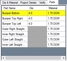
- The Parts tab will contain each individual part in the current project. Here, you can assign a specific die and material to any given part. This will reflect on the design in the display screen and will alter the bending instructions accordingly.
- Here, you can select the part(s) that you'd like to transfer to a single part designer in order to receive the bending instructions. If you'd like to transfer the entire project to an Assembly, simply click away from the Parts tab before transferring.
- Need help transferring? Click on the video link here --> https://www.youtube.com/watch?v=oiqm0TsRoOo
Display
Once a template in APT is selected, the project will appear in the display window. In the upper left-hand corner of the display screen there are three buttons. These buttons represent the following in order from left to right.
![]()
- Toggle the display in front of or behind the legend.
- Print the legend.
- See the legend in a new window.
This will be the standard layout for all Armor Pack Templates as they will appear in your software.
Transfer Interface
When transferring a single part or assembly of multiple parts from any designer to the Assembly designer, the user can refer to this guide for assistance.
The Transfer Menu
- When transferring a part to Assembly, select the project in the display area, or a number or parts from the parts list and select the "Transfer Drop Down Menu"
 at the top of the screen on the Icon Toolbar.
- From there, the options that are available include the "New Assembly" option, or the "Existing Assembly" option. Select the option that corresponds with the desired assembly project to begin the transferring process.
- Upon transferring, a window will appear asking if you'd like to automatically place this project into the design. If you select Yes, the project or part will be placed into the design and anchored to the Tri-Star. If you select No, the project or part will be attached to your cursor so that you can click on a point of your choice to place it there.
In the event that you select the No button, this project or part will remain attached to your cursor until you switch away from the Main tab.
