SE Options
Bend-Tech 7x Wiki :: Main Menu Bar :: Tools :: Options
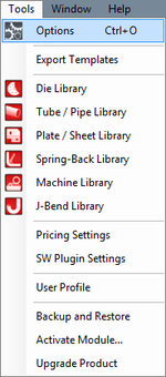
This menu can be accessed by clicking the Tools option on the main menu bar and selecting Options from the drop down menu.
Additionally, when adjusting any of these settings, be sure to click the Save button ![]() at the bottom of the frame to apply the new defaults or settings. When any default settings are changed, any designs that are currently open will not be affected. Any new designs or designs opened after changes were made will have these settings applied.
at the bottom of the frame to apply the new defaults or settings. When any default settings are changed, any designs that are currently open will not be affected. Any new designs or designs opened after changes were made will have these settings applied.
To access the options menu, click on the Tools menu on the Main Menu Bar and select Options in the drop down menu
...or click on the Settings link on the Task Menu.
Contents
General
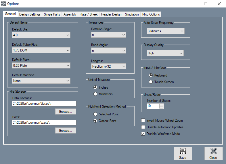
Default Items
- Default Die: In the Default Die menu, a die can be chosen and set as the default. Once a die is set as the default, it will be the die that is initially selected when a new single part is created. To set a default die, click the drop down menu and select a die from the list.
- Default Tube/Pipe: In the Default Tube/Pipe menu, a tube/pipe material can be chosen and set as the default. Once a material is set as the default, it will be the material that is initially selected when a new single part is created.
- Default Plate: In the Default Plate menu, a plate material can be chosen and set as the default. Once a plate material is set as the default, it will be the material that is initially selected when a new plate is created.
- Default Machine: In the Default Machine menu, a machine can be chosen and set as the default. Once a machine is set as the default, it will be the machine that is initially selected when a new part is created.
File Storage
The file storage locations will determine where data (die, material, plate, etc.) libraries and part files will be stored.
- Data Libraries: To choose a new location for the data libraries, click the "Browse"..." button
 below the data libraries location.
- Parts: To choose a default location for part files, click the "Browse:..." button
 below the parts location. This will be the folder that is initially opened when a part is being saved.
- "It is recommended that you stick with the default file locations for the part and data libraries. It will be easier for our company to find them if there is ever a problem with your computer which affects the software."
Tolerances
The decimal tolerance for the lengths, angles, and rotations can be adjusted here. The decimal tolerance controls how many digits will be allowed after decimals points for length, angle, and rotation. In the tolerance options, each digit place is represented by an n.
(For example, if the angle tolerance is set to n.nn and the actual angle is 90.539°, the angle will be rounded to 90.54°. If the angle tolerance is set to just n, then the angle would be rounded to 91°.)
- Rotation Angle: To change the decimal tolerance for part rotation values, click the drop down menu and select a tolerance option from the list.
- Bend Angle: To change the decimal tolerance for bend angle values, click the drop down menu and select a tolerance option from the list.
- Lengths: Length values can be displayed in either fractional or decimal format. To change the format and/or tolerance for lengths, click the drop down menu and select an option from the list.
Unit of Measure
- The measurement units can be set to either "Inches:" or "Millimeters:". Once a unit of measure is chosen, it will be the unit of measure that is initially chosen wherever units of measure can be adjusted throughout the software.
PickPoint Selection Method
- The "PickPoint Selection Method:" will determine how pickpoints can be selected in the plate and assembly interfaces. The "Selected Point:" option will require a point to be directly clicked on in order to be selected. The "Closest Point:" option will select whichever point is closest to the cursor when it is clicked.
Auto-Save Frequency
- Using the "Auto-Save Frequency:" drop down menu, the time interval between auto-saves can be adjusted or the function can be turned off. This setting will affect any open designs throughout the software.
Display Quality
- Using the "Display Quality:" drop down menu, the quality of the graphical representation of parts, plate designs, or assemblies can be adjusted. To change this setting, click on the drop down menu and choose either Low, Medium, or High.
Input/Interface
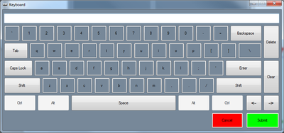
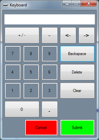
- The type of input device used with the software can be specified here. For a standard computer and keyboard setup, the "Keyboard:" option would be appropriate. If a touchscreen computer/computer without a keyboard, select the "Touch Screen:" option. When this option is chosen, a keyboard/number pad will open on-screen whenever text or a numerical value is needed to be entered. (See the images below.)
Undo/Redo
- The number of steps allowed for redo/undos can be adjusted here. For example, if 10 is set as the number of steps, the undo button can be hit 10 times before it no longer has an affect on the plate or assembly design. There is a limit to 100 steps.
Invert Mouse Wheel Zoom
- Check the "Invert Mouse Wheel Zoom:" checkbox to reverse the zoom direction from the default (scrolling up to zoom out and scrolling down to zoom in) to the inverted setting (scrolling up to zoom in and scrolling down to zoom out).
Disable Automatic Updates
- When the "Disable Automatic Updates:" checkbox is clicked, automatic software updates will be disabled.
Disable Wireframe Mode
- When the "Disable Wireframe:" checkbox is clicked, wireframe mode will not be available.
Design Settings
Rotation
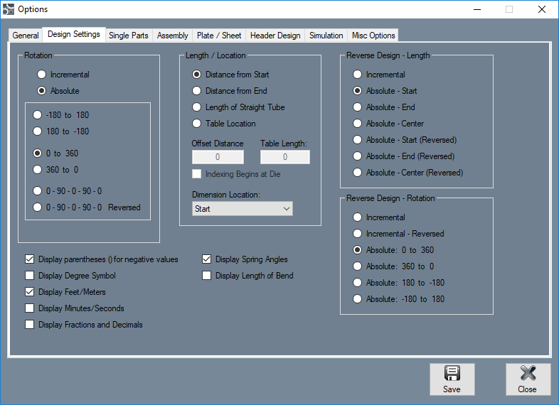
The rotation settings control how rotation values are displayed in the results table. Rotation can be measured in incremental or absolute terms. Each rotation angle range can also be chosen.
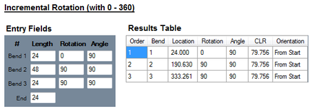
- Incremental: Select the "Incremental:" option and rotation angles will start from the end of the previous bend's rotation.
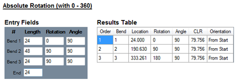
- Absolute: Select the "Absolute:" option and rotation angles will always start from the very beginning of the angle scale.
- Angle Scale: The rotation scale will determine what the rotation angles will range between. The rotation scale will show where the angle measurements begin and where they end. Choose a rotation scale by clicking on one of the scale options. The rotation scales available are 0 - 360, 360 - 0, (-180) - 180, and 180 - (-180). The 0 - 90 - 0 - 90 - 0 and 0 - 90 - 0 - 90 - 0 Reversed options will be added when the Absolute option is chosen.
Display Settings
In the bottom left corner there will be a list of checkbox options to control the display options for the results table on single part designers.
- Display parentheses () for negative values: Check this box to have all negative values enclosed in parentheses.
- Display Degree Symbol: Check this box for angle values to have degree symbols shown next to them.
- Display Feet/Meters: Check this box for large length values to be displayed in terms of feet or meters (feet will be used if inches are used as the units and meters will be used if millimeters are the units.)
- Display Minutes/Seconds: Check this box for angle values to be displayed in terms of minutes and seconds instead of decimal degree values.
- Display Fractions and Decimals: Check this box to have the total cut length of the part design (displayed above the results table) represented in terms of fractions and decimals. The decimal/fraction tolerance of this value will be determined by the length tolerance which can be set up in the Options menu in the General Tab or in the Part Settings menu in the Output Results tab.
- Display Spring Angles: Check this box for spring angle values to be included in the results table.
- Display Length of Bend: Check this box to have length of bend values included in the results table.
Length/Location
The length/location setting will determine how the bend location will be calculated in the results table.
- Distance from Start: Bend locations will be measured from the starting edge of the tube.
- Distance from End: Bend locations will be measured from the ending edge of the tube.
- Length of Straight Tube: Bend location values will be the amount of straight tube between each bend.
- Table Location: Bend locations will be based on index table values. If this option is used, the offset distance between the table and the bend will need to be supplied as well as scale length of the table. Check the Indexing Begins at Die option if the scale begins at the die.
- Dimension Location: This option determines where the bend location marks will be placed in reference to the bend. Bend locations can be placed at the start, center, or end of each bend.
Reverse Design - Length
This setting will determine how inputted part lengths are interpreted when creating a reverse design part.
- Incremental: Entered length values start from the previous bend.
- Absolute - Start: Entered length values are the distance from the starting edge of the tube to the starting edge of each bend.
- Absolute - End: Entered length values are the distance from the ending edge of the tube to the ending edge of each bend.
- Absolute - Center: Entered length values are the distance from the starting edge of the tube to the center of each bend.
- Absolute - Start(Reversed): Entered length values are the distance from the end of the part to the start of each bend.
- Absolute - End(Reversed): Entered length values are the distance from the end of the part to the end of each bend.
- Absolute - Center (Reversed): Entered length values are the distance from the end of the part to the center of each bend.
Reverse Design - Rotation
This setting will determine how rotations will be calculated in the results table when creating a reverse design part.
- Incremental: Entered rotation values start from the end of the previous rotation.
- Incremental - Reversed: Entered rotation values start from the end of the previous rotation with a reversed direction.
- Absolute: 0 to 360: Entered rotation values always start from the beginning of the angle scale (0) at each rotation.
- Absolute: 360 to 0: Entered rotation values always start from the beginning of the angle scale (360) at each rotation.
- Absolute: 180 to -180: Entered rotation values always start from the beginning of the angle scale (180) at each rotation.
- Absolute: -180 to 180: Entered rotation values always start from the beginning of the angle scale (-180) at each rotation.
Single Parts
Features to Display
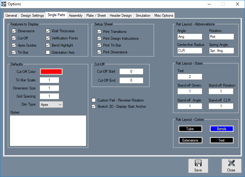
These settings will determine the kind of features that will be displayed on the part model in any of the single part design interfaces. Click the check boxes next to the features you want to have shown.
- Dimensions: Length measurement values will be displayed on the part lengths.
- Cut-Off: If any cut-off is added to the part, it will be represented on the part display.
- Apex Guides: For each bend, guidelines will extend from the part model to the verification points.
- Tri-Star: The axis will be shown on the graphical display.
- Wall Thickness: The thickness of the material will be shown on the 3D part model.
- Verification Points: Points will be displayed at the apex of each bend.
- Bend Highlight: The current bend will be highlighted in red on the 3D part model.
- Orientation Axis: The orientation axis will be displayed in the bottom left corner of the part display.
Defaults
- Cut-Off Color: This will be the default color that will be used to represent the sections of cut-off on the 3D part model.
- Tri-Star Scale: The default scaling value for the axis.
- Dimension Size: The default dimension size.
- Dim Type: The default dimension type that will be selected in the Dim Type menus for each bend.
- Notes: The default notes that will be generated in the notes area for new part designs.
Setup Sheet
- Print Transitions: The transition sheet will include a chart that displays the location, rotation, and bend angle values for each bend on the part. Each location, rotation, and angle will have a image of the 3D part showing what the part will look like at that specific stage. By default, these instructions will be included on the print out while this option is checked.
- Print Design Instructions: By default, the design instructions chart will be included on the print out while this option is checked.
- Print Tri-Star: By default, the part model will have the tri-star included on the print out while this option is checked.
- Print Dimensions: By default, the part model will have the dimension markers and values included while this option is checked.
Cut-Off
- The default cut-off start and end values can be defined here. Each new part will automatically have these cut-offs initially applied.
Custom Part - Reverse Rotation
- Check this box to reverse the rotation direction while using the Custom Part design interface.
Flat Layout - Abbreviations
- These settings will determine the abbreviations used for angle, rotation, centerline radius, and spring angles in Flat Layout.
Flat Layout - Sizes
- These settings will determine the sizes for text, stand-off dimension, angle, rotation, and CLR values in Flat Layout. To change the size, enter a value into the size fields.
Flat Layout - Colors
- These settings will determine the colors for tubes, bends, extensions, and text in Flat Layout. To change the colors, click the corresponding button to change the color of a specific feature.
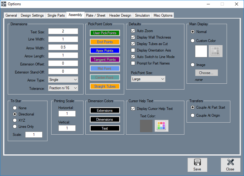
Assembly
Dimensions
- Using these settings, the size for the text, line and arrow width, arrow length, and extension offset and stand-off can be determined. To change these sizes, enter a value into the fields. The arrow type determines the kind of arrow that will be used on the dimension markers. To change the arrow type, click the arrow type menu and select a type. The tolerance will determine the format and/or tolerance of the dimension values. To change the tolerance, click the tolerance menu and choose an option.
Tri-Star
- These options will control how the tri-star will appear in the assembly designer. The tri-star can be directional (labeled with ceiling/floor, front/back, left/right), XYZ (labeled with X, Y, and Z), Lines Only, or not shown at all. The default scale value can also be defined here.
Printing Scale
- The printing scale for cutting wrapper print outs can be determined here. Enter a value into the vertical and/or horizontal fields to apply a scale.
PickPoint Colors
- The colors of the different PickPoint types can be chosen here. To change the color of a PickPoint, click the corresponding button and select a color.
Dimension Colors
- The colors of the dimension marker, extensions, and values can be chosen here. To change the colors of any of these features, click on the corresponding button and select a color.
Defaults
- Auto Zoom: While auto zoom is on, the screen will automatically zoom out if any features being added are outside the current frames boundaries.
- Display Wall Thickness: While this option is activated, the wall thickness of the tube will be displayed if the 3D shaded or 3D wireframe options are chosen.
- Display Tubes as Cut:
- Display Orientation Axis: While this option is enabled, the orientation axis will be displayed in the bottom left corner of the assembly display.
- Auto Switch to Line Mode: This option will automatically switch the mode to line mode when PickPoints are being placed.
- Prompt for Part Names: While this option is enabled, whenever new parts are added to the assembly, a prompt will appear where the new part can be given a name.
- PickPoint Size: The default size of the PickPoints can be chosen here.
Cursor Help Text
- Cursor help text is displayed next to the cursor while the assembly to help guide the user through certain tasks in the interface. Check the box next to Display Cursor Help Text to have these instructions shown. The text color option will change the color of the cursor help text. Click the color button to adjust this setting.
Main Display
- The background of the display frame in the assembly interface can be set to a plain white background, a custom color, or an image.
Transfers
- When transferring a part to an Assembly design, the coupler (or anchor) for the set origin of the part can be designated here. Couple At Part Start will place the coupler where the part started. Couple At Origin will place the coupler at the origin of the part. These differ only by the way they were created.
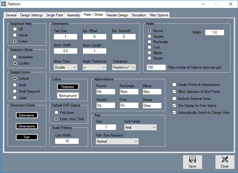
Plate/Sheet
Graphical Help
- This will determine how and if any help text will be displayed. Choose the Off option to have no help displayed in the plate designer. Choose the Actual option to
- Chose the Cursor option to have the help text displayed right next to the cursor.
Selection Mode
- If confirm is chosen, every time features are to be deleted, moved, scaled, or copied, a window will appear to confirm the action before it is actually executed. Otherwise, the action will be performed immediately.
Design Cursor
- The type of cursor used while creating a plate design can be chosen. Default will be the standard cursor, Small is a cross shape, small diagonal is an X shape, and large is a cross-hair style cursor that fills the whole design frame.
Dimension Colors
- The colors of the extensions, dimension markers, and dimension text in the plate designer can be determined using these options. To change the color of any of these features, click on the corresponding button and select a color.
Dimensions
- Using these settings, the size for the text, line and arrow width, arrow length, and extension offset and stand-off can be determined. To change these sizes, enter a value into the fields. The arrow type determines the kind of arrow that will be used on the dimension markers. To change the arrow type, click the arrow type menu and select a type. The tolerance will determine the format and/or tolerance of the dimension values. To change the tolerance, click the tolerance menu and choose an option. The angle tolerance will determine the decimal places allowed for angle measurements. To change the angle tolerance, click the angle tolerance menu and select an option from the drop down menu.
Colors
- The colors of the features and background can be adjusted using these settings. To change the color of either of these, click on the corresponding button and select a color.
Default DXF Output
- The output for DXF files can be determined here. These files will be output as PolyLines or as Lines, Arcs, and Text.
Scale Printing
- The default value for the width of the line representing the part features in the Print Scale tool can be adjusted here. Smaller values will result in thinner lines while larger numbers will result in thicker lines.
Abbreviations
- The abbreviations for dimensions in the plate design interface can be determined here. When any of these features are labeled with a dimension, this abbreviation will be used to identify it.
Text
- The size, font, and text path precision of dimensions can be determined here. To change the text size, enter a value into the size field. To change the font, click on the drop down menu and select a font from the list. The path text precision can be adjusted by clicking the drop down menu and selecting an option from the list.
Holes
- The default width, angles, lengths, corner radii, and maximum number of holes to draw in a grid can be supplied here for each hole type. These are only the default settings and can be changed within the plate interface.
Extra Options
- Create Points at Intersections: Check this option to have points automatically created at any line intersections in plate designs.
- Allow Selection of End Points: This option will allow of the ends of features to be selected.
- Exclude External Holes: Check this option to ignore all holes outside the plate's boundary lines while the plate is being defined
- Dim Display for Free Select: Check this option to have the display frame dimmed to a grey shade whenever free select is activated.
- Automatically Switch to Design View: Check this option to have the display mode automatically switched back to 'Design' if it is in any other mode and any attempts are made to edit the design.
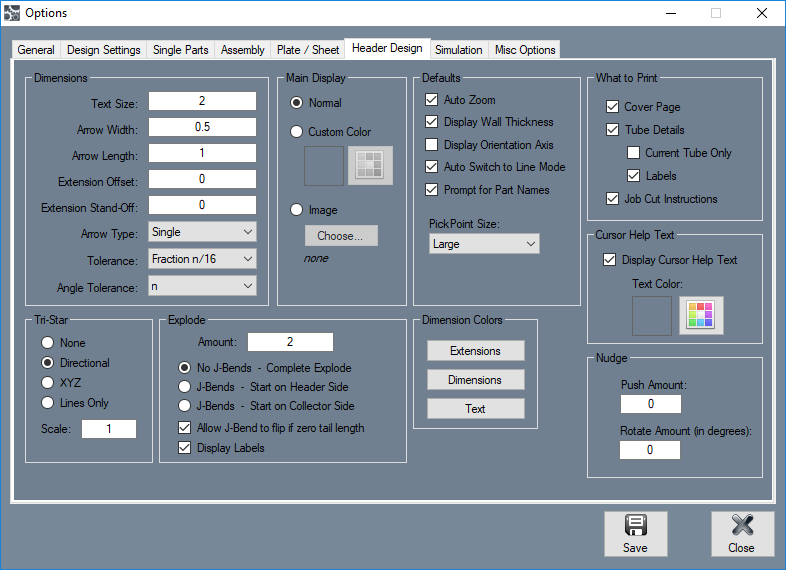
Header Design
Dimensions
- Using these settings, the size for the text, line and arrow width, arrow length, and extension offset and stand-off can be determined. To change these sizes, enter a value into the fields. The arrow type determines the kind of arrow that will be used on the dimension markers. To change the arrow type, click the arrow type menu and select a type. The tolerance will determine the format and/or tolerance of the dimension values. To change the tolerance, click the tolerance menu and choose an option. The angle tolerance will determine the decimal places allowed for angle measurements. To change the angle tolerance, click the angle tolerance menu and select an option from the drop down menu.
Tri-Star
- These options will control how the tri-star will appear in the header designer. The tri-star can be directional (labeled with ceiling/floor, front/back, left/right), XYZ (labeled with X, Y, and Z), Lines Only, or not shown at all. The default scale value can also be defined here.
Main Display
- The background of the display frame in the assembly interface can be set to a plain white background, a custom color, or an image.
Explode
These settings will determine the default explode amount, explosion type, and explosion settings.
- Amount: This amount will determine the distance between sections once the header has been exploded.
- No J-Bends - Complete Explode: This option will make it so each J-Bend will be broken into a separate bend section instead of a J shape.
- J-Bends - Start on Header Side: This option will make it so the long tail end of each J-Bend will start towards the header end of the tube
- J-Bends - Start on Collector Side: This option will make it so the long tail end of each J-Bend will point towards the collector end of the tube.
- Allow J-Bend to flip if zero tail length: This option to flip the J-Bend around to point the opposite direction if the tail length of the bend is zero.
- Display Labels: Check this box to have each section of the header tubes labeled. The labels will display the part number followed by a hyphen and the J-Bend number.
Defaults
- Auto Zoom: While auto zoom is on, the screen will automatically zoom out if any features being added are outside the current frames boundaries.
- Display Wall Thickness: While this option is activated, the wall thickness of the tube will be displayed if the 3D shaded or 3D wireframe options are chosen.
- Display Tubes as Cut:
- Display Orientation Axis: While this option is enabled, the orientation axis will be displayed in the bottom left corner of the assembly display.
- Auto Switch to Line Mode: This option will automatically switch the mode to line mode when PickPoints are being placed.
- Prompt for Part Names: While this option is enabled, whenever new parts are added to the assembly, a prompt will appear where the new part can be given a name.
- PickPoint Size: The default size of the PickPoints can be chosen here.
Dimension Colors
- The colors of the extensions, dimension markers, and dimension text in the header designer can be determined using these options. To change the color of any of these features, click on the corresponding button and select a color.
What to Print
- These are the default setup sheet printing options. Check the box next to Cover Page' to have a front page with general information about the header printed with the setup sheet. Check the box next to Tube Details to have chart containing details about each tube. Check the box next to Current Tube Only to only print tube details for the tube that is currently highlighted in the list of tubes. Check the box next to 'Labels' to have each section of the tube labeled. Check the box next to Job Cut Instructions to have instructions on how to create the header design printed with the setup sheet.
Cursor Help Text
Cursor help text is displayed next to the cursor while the header designer to help guide the user through certain tasks in the interface. Check the box next to Display Cursor Help Text to have these instructions shown. The text color option will change the color of the cursor help text. Click the color button to adjust this setting.
Nudge
- The default push and rotate amount can be set here. Push Amount is how far the tube will be moved when nudged. Rotate Amount is how many degrees will be tube will be rotated when nudged.
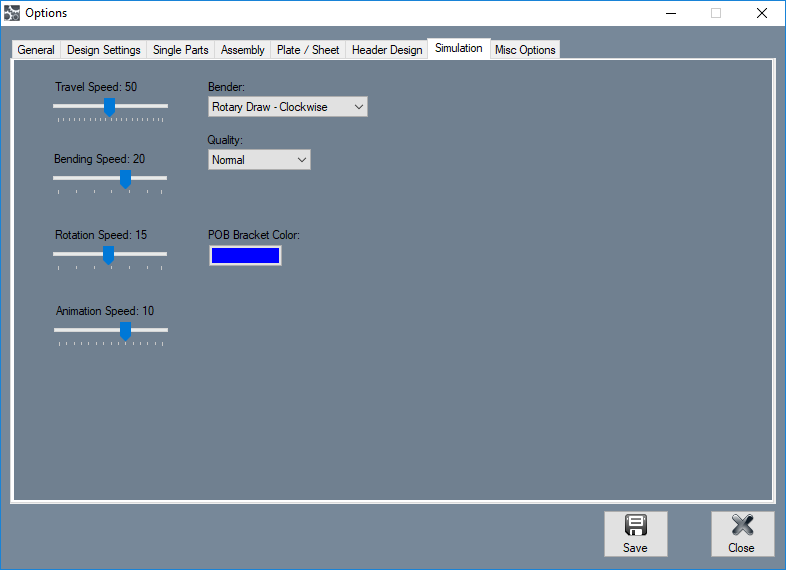
Simulation
In the Simulation tab, the default travel, bend, rotation, and animation speed, as well as the default bender type, simulation quality and POB bracket color can be set. These settings are only defaults and can be adjusted while viewing the simulation.
Speeds
- The default speeds of the travel, bending, rotation, and animation can be adjusted independently. To adjust the speeds, click and drag the point back and forth.
Bender
- The bender chosen here will determine the type of bender used in simulation. The bender options available are: center compression, rotary compression - clockwise, rotary compression - counter clockwise, rotary compression - vertical, rotary draw - clockwise, rotary draw - counter clockwise, and rotary draw - vertical.
Quality
- The display quality of the simulation animation can be adjusted here. To adjust the simulation, click on the drop down menu and choose a quality option.
POB Bracket Color
- The default color of the POB bracket shown in the simulation can be determined here. To change the color, click on the button and select a color.
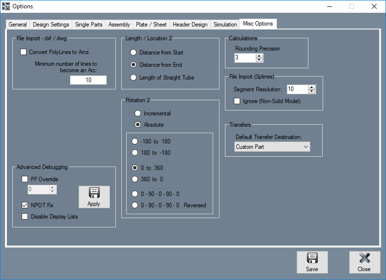
Misc Options
File Import - dxf/dwg
- These settings will effect any dxf or dwg files that are imported into the software. If the Convert Polylines to Arcs option is checked, imported files with polylines that meet the minimum number of lines supplied in the field below will be converted to a single arc.
Length/ Location 2
This setting allows a second location type to be defined. This will only affect the Export Template tool, where the Location 2 option is shown in the Bend Data Table drop down menus.
- Distance from Start: Bend locations will be measured from the starting edge of the tube.
- Distance from End: Bend locations will be measured from the ending edge of the tube.
- Length of Straight Tube: Bend location values will be the amount of straight tube between each bend.
Rotation 2
This setting allows a second rotation type to be defined. This will only affect the Export Template tool, where the Rotation 2 option is shown in the Bend Data Table drop down menus.
- Incremental: Rotation angles will start from the end of the previous bend's rotation. Click the incremental rotation option to select it.
- Absolute: Rotation angles will always start from the very beginning of the angle scale. Click the absolute rotation option to select it.
- Angle Scale: The rotation scale will determine what the rotation angles will range between. The rotation scale will show where the angle measurements begin and where they end. Choose a rotation scale by clicking on one of the scale options. The rotation scales available are 0 - 360, 360 - 0, (-180) - 180, and 180 - (-180). The 0 - 90 - 0 - 90 - 0 and 0 - 90 - 0 - 90 - 0 Reversed options will be added when the Absolute option is chosen.
Calculations
- The decimal rounding precision can be specified in the Rounding Precision field. This precision value will be used to determine how many decimal places to round converted values (when using the Inch vs MM function, for example).
File Import (Splines)
- The Segment Resolution is the set resolution of splines. A larger number will result in a higher resolution spline, but also increases the number of entities that are to be processed.
- The Ignore (Non-Solid Model) check box can be checked which will cause any splines to be ignored during the import of a .step/.iges file. This only applies to the standard importing options and does not apply to the solid model import.
