Adjust Centerline
Bend-Tech 7x Wiki :: Single Part -Interface/General Functions :: Adjust Centerline
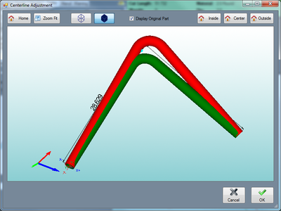
The Adjust Centerline tool allows how the part measurements are interpreted and will apply these changes to the part design. In the part designers, parts are assumed to be based on centerline. This tool allows the current part dimensions to be from the inside or outside of the tube instead.
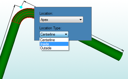
To change the Location and/or Location Type for a bend, first select the bend by clicking on it in the part display. A menu will appear where the location and location types can be adjusted. Click on either of the drop down menus to choose new options.
Once a new location or location type has been chosen, a red preview reflecting the location changes will appear. The original part will be shown in green.
Click the Home button ![]() to set the part preview to the default location and orientation.
to set the part preview to the default location and orientation.
Click the Zoom Fit button ![]() to zoom all the way in on the current view of the 3D part display and fit it to the display frame.
to zoom all the way in on the current view of the 3D part display and fit it to the display frame.
The part model can be shown in either wire frame or as a solid shaded model. Click on the wireframe button ![]() to show the model in wireframe. Click on the shaded button
to show the model in wireframe. Click on the shaded button ![]() to show the model as a shaded part.
to show the model as a shaded part.
Check the box next to Display Original Part to have the original part shown after changes are made to the locations.
Click the Inside button ![]() to set the locations for all of the bends to inside.
to set the locations for all of the bends to inside.
Click the Center button ![]() to set the locations for all of the bends back to centerline.
to set the locations for all of the bends back to centerline.
Click the Outside button ![]() to set the locations for all of the bends to outside.
to set the locations for all of the bends to outside.
Click the OK button ![]() to take the location and location type adjustments and apply them to the current part design.
to take the location and location type adjustments and apply them to the current part design.

