Header - Dimensions
Bend-Tech 7x Wiki :: Header Design :: Dimensions
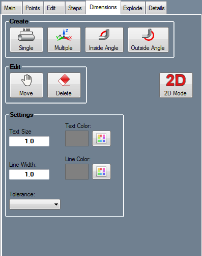
Create
Single
Click the Single button  to place a single dimension. First, select a line feature or two points that the dimension will be placed between. Then choose a placement location for the dimension text.
Multiple
Click the Multiple button  to place multiple dimensions along a specified area of an assembly. First, select a line feature where the dimensions will start, then select end point of the dimensions. Between these features, each possible dimension will be placed.
Inside Angle
Click the Inside Angle button  to place an angle measure dimension at the inside of the intersection of two lines. First, select a line or reference point to represent the beginning of the dimension. Next, select the inside point of the line and/or the second reference line. Last, choose a location to place the dimension text.
Outside Angle
Click the Outside Angle button  to place an angle measure dimension around the outside angle of the reference lines. First, select a line or reference point to represent the beginning of the dimension. Next, select the inside point of the line and/or the second reference line. Last, choose a location to place the dimension text.
Edit
Move
Click the Move button  to relocate the text and marker of a dimension. First select the dimension that will be moved. Next, using the cursor, click on a new location to place the dimension.
Delete
To delete dimensions, click the Delete button  and click on a dimension(s) to delete them.
Settings
The appearance of dimension text and markers can be adjusted using these settings.
- Text Size: The size of the dimension text can be supplied here. Larger values will result in larger dimension font size and vice versa.
- Text Color: The color of the dimension text can be chosen here. Click the color button and select a color to adjust text color.
- Line Width: The width of the dimension markers can be given here. Larger values will result in thicker dimension lines and vice versa.
- Line Color: The color of the dimension marker lines can be chosen here. Click the color button and select a color to adjust line color.
- Tolerance: The decimal tolerance for the dimension values can be adjusted here. The decimal tolerance controls how many digits will be allowed after these values. In the tolerance options, each digit place is represented by an n.
- Dimension values can be displayed in either fractional or decimal format. To change the format and/or tolerance for lengths, click the drop down menu and select an option from the list.
- Display Dimensions: Check the box next to Display Dimensions to have the dimensions placed on the assembly design. Uncheck this box to hide the dimension markers and values.
2D Mode
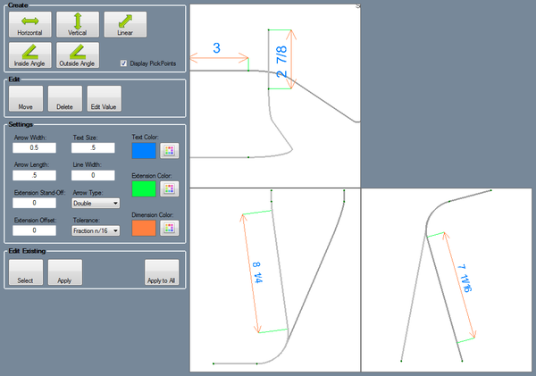
In 2D Mode, the assembly will be shown from the top, left, and right. Dimensions can then be placed on these different views of the assembly. The display can be printed using File --> Print or by clicking the Print icon.
Create
- Horizontal: Click the Horizontal button
 to place a horizontal dimension along a selected line or between two selected PickPoints.
- Vertical: Click the Vertical button
 to place a vertical dimension on a vertical line or between two selected pickpoints.
- Inside Angle: Click the Inside Angle button
 to place an inside angle dimension at the intersection of two lines. First, select a line or reference point to represent the beginning of the dimension. Next, select the inside point of the line and/or the second reference line. Last, choose a location to place the dimension text.
- Outside Angle: Click the Outside Angle button
 to place an outside angle dimension around the intersection of two lines. First, select a line or reference point to represent the beginning of the dimension. Next, select the inside point of the line and/or the second reference line. Last, choose a location to place the dimension text.
Edit
Click the Move button  to relocate the text and marker of a dimension. First select the dimension that will be moved. Next, using the cursor, click on a new location to place the dimension.
To delete a dimension, click the Delete button  and click on a dimension.
Click the Edit Value button  to change the value of a dimension. First, click on a dimension. Then enter the new value in the edit value window and click the OK button.
Settings
- Arrow Width: This is the width of the arrows at the ends of the dimension line. Enter a value in this field to define the arrow width. Larger values will result in wider arrows and vice versa.
- Arrow Length:This is the length of the arrows at the ends of a dimension line. Enter a value in this field to define the arrow width. Larger values will result in longer arrows and vice versa.
- Extension Stand-Off: This is the distance between the extension lines and the entity that the dimension is measuring.
- Extension Offset: This is the distance that the extension lines extend beyond the dimension line.
- Text Size: The size of the dimension text can be supplied here. Larger values will result in larger dimension font size and vice versa.
- Line Width: The width of the dimension markers can be given here. Larger values will result in thicker dimension lines and vice versa.
- Arrow Type: This is the shape of the arrows at the ends of a dimension line. Click on the menu next to Arrow Type in the value column and select an option from the drop down menu.
- Tolerance: The decimal tolerance for the dimension values can be adjusted here. The decimal tolerance controls how many digits will be allowed after these values. In the tolerance options, each digit place is represented by an n.
- Dimension values can be displayed in either fractional or decimal format. To change the format and/or tolerance for lengths, click the drop down menu and select an option from the list.
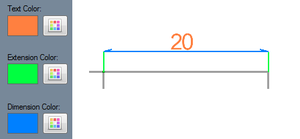
- Text, Extension, and Dimension Color: The colors of the dimension text, extensions can be changed using these color options. To change the color of a feature, click on the corresponding button and select a color from the menu. (See the image to the right)
Edit Existing
Click the Select button and click on a dimension to view and/or edit its settings, which will be generated in the Settings area above.
Click the Apply button to apply any setting changes made to the currently selected dimension.
Click the Apply to All button to apply the currently selected dimension settings to every dimension.


