Difference between revisions of "Single Part -Interface/General Functions"
| (32 intermediate revisions by the same user not shown) | |||
| Line 1: | Line 1: | ||
| − | '''[[Main Page|Bend-Tech 7x Wiki]] :: Single Part | + | '''[[Main Page|Bend-Tech 7x Wiki]] :: Single Part Interface/General Functions''' |
| − | + | ||
[[File:single_part_1.png|right|450px]] | [[File:single_part_1.png|right|450px]] | ||
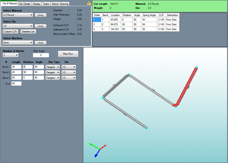
| − | Whenever a single part (Template, Custom Part, Custom 3D Part, XYZ Part, Sketch 3D, Sketch 2D, Reverse Design, or Straight Part) is being created, the interface will generally be the same for each with the exception of the part information/creation section below the tabbed menu. | + | *Whenever a single part (Template, Custom Part, Custom 3D Part, XYZ Part, Sketch 3D, Sketch 2D, Reverse Design, or Straight Part) is being created, the interface will generally be the same for each with the exception of the part information/creation section below the tabbed menu. |
| − | The screen is broken up into four sections with a small icon menu near the top of the frame. The top | + | *The screen is broken up into four sections with a small icon menu near the top of the frame. The top left corner holds the tabbed section, the top right corner holds the results table, the bottom right holds the 3D display area, and the bottom left is the part information/creation section; usually containing value fields to create the user's desired design more easily. |
| Line 18: | Line 18: | ||
| + | ==Tabs== | ||
| + | In the top left corner, there is a tabbed section that holds a majority of the design options. | ||
| + | ==Die & Material== | ||
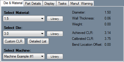
| + | Under the Die & Material tab, the material and die can be chosen. | ||
| + | [[File:single_part_4.png|right]] | ||
| + | '''To select a die''', choose one from the drop down menu below 'Select Material:'. To see more detailed information about each material, click the 'Library' button next to the material menu to view the material library. To the right of the material selection, the diameter, wall thickness, and weight of the selected material will be displayed. | ||
| + | '''To select a die''', choose one from the drop down menu below 'Select Die:' or click the 'Detailed List' button. Once the 'Detailed List' button has been clicked, a new window containing a chart of every die in the die library along with detailed information about each. To select a die from this list, click on a die and click the 'Select' button or double click on the desired die. To print this list, click the 'Print' button. Click the 'Library' button next to the die menu to view the die library. | ||
| + | |||
| + | '''To create a custom die CLR''', click the 'Custom CLR' button. Enter the CLR value and click 'OK'. This will add the entered CLR value to the die drop down menus (next to each bend) as 'Custom CLR - (Entered Value). Select the custom CLR from the menu to use it.To the right of the die selection, the CLR, calibrated CLR, and bend location offset of the selected die will be displayed. | ||
| − | |||
| − | [[File: | + | ==Part Details== |
| + | [[File:single_bend_part1.png|right]] | ||
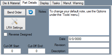
| + | *Under the Part Details tab, notes, revision information, part description, cut-off start/end values, and the bend order menu can be accessed. | ||
| − | + | *To add '''notes''', type in the "'''Notes'''" field below. Any notes shown here will be included on the setup sheet. To set a default note, Select "'''Options'''" under the '''Tools''' menu and go to the '''Single Parts''' tab. If desired, enter any revision information next to "'''Revision'''" and a description next to "'''Description'''". | |
| − | + | *Type in any '''cut-off''' values into the "'''Cut-Off Start'''" and/or "'''Cut-Off End'''" fields. These cut-off values are the amount of extra material needed on either end of the part when bending. | |
| − | + | *Check the "'''Reverse Designed'''" check box to specify whether that part is designed from the opposite end of the current design. | |
| − | + | *Select the "'''Bend Order'''" button [[File:bendorder_1.png]] to access the '''Part Bending Order''' menu. In this window users can view their part being bent in a simulation. This window also contains settings and bending options. See the '''[[Bend Order]]''' page for further information on this feature. | |
| − | + | *Select the "'''Reset Bend Order'''" [[File:bendorder_10.png]] button to reset the bend order back to normal. | |
| − | + | *Select the "'''Part Settings'''" [[File:part_settings.png]] button to adjust the general settings, results/output settings, and reverse design settings for the current part. See the '''[[Part Settings]]''' page for further information on this feature. | |
| − | + | ==Display== | |
| + | [[File:single_part_6.png|right]] | ||
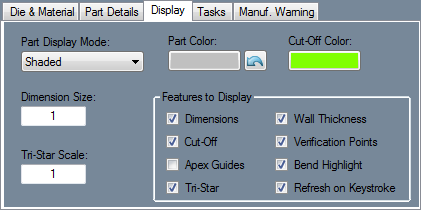
| + | Under the "'''Display'''" tab, settings specific to the 3D part display can be adjusted. Select the button below "'''Cut-Off Color'''" to change the color that cut-off lengths will be displayed in. This button will display the current color that is in use. To change the size of the Tri-Star or Dimension text, enter values into either of the '''Tri-Star Scale''' or '''Dimension Size''' field. | ||
| − | + | Check the box next to '''Dimensions''' to have the length measurements and markers displayed in the part display. | |
| − | + | Check the box next to '''Cut-Off''' to have any cut-off lengths that were entered in the 'Cut-Off Start or End' fields in the Part Details tab shown in the part display. | |
| − | + | Check the box next to '''Apex Guides''' to to show lines extending from the bend verification points to the part. | |
| − | + | Check the box next to '''Tri-Star''' to have the XYZ compass/tri-star displayed in the part display. | |
| − | + | Check the box next to '''Wall Thickness''' to have the thickness of the material shown on the part model when in shaded mode. | |
| − | + | Check the box next to the '''Verification Points''' to display blue points on the apex of each bend and the start and end of the part. | |
| − | + | Check the box next to '''Bend Highlight''' to have whichever bend is currently selected (either the cursor is in the design field or selected in the bend list) highlighted on the part model. | |
| − | + | Check the box next to '''Refresh on Keystroke''' to have the part model constantly updated whenever changed are made to the design. | |
| − | |||
| + | While any of these options are unchecked, they will not be shown in the current 3D part display area. | ||
| − | |||
| − | |||
| − | |||
| − | |||
| − | |||
| − | |||
| − | |||
| − | |||
| − | |||
| − | |||
| − | |||
| − | |||
| − | |||
| − | |||
| + | ==Tasks== | ||
| + | [[File:single_part_3.png|right]] | ||
| − | + | *"'''Those below with simple functions that are self-explanatory will not have a link to further explanation for how to use the function.'''" | |
| − | |||
| − | |||
| − | ''' | ||
| − | + | '''[[Verify]]''' | |
| + | *Select the "'''Verify'''" [[File:verify.png]] button to open the '''Part Verify''' window. Using this tool, the dimensions/distances and the angle between two points can be verified. | ||
| − | '''[[ | + | '''[[Flat Layout]]''' |
| + | *Select the "'''Flat Layout'''" [[File:flatlayout.png]] button to open the '''Flat Layout''' window. Two flat, unbent models of the same part will be displayed and can be labeled and then printed out. | ||
| + | '''[[Bump Bending]]''' | ||
| + | *Select the "'''Bump Bending'''" [[File:bumpbending.png]] button to add bump bends to a bend on the current part. Bump bending allows bends to be sectioned off into multiple smaller, equal sized bends. | ||
| − | |||
| − | |||
| − | |||
| − | |||
| − | + | '''[[Price]]''' | |
| + | *Select the "'''Price'''" [[File:price.png]] button to access the '''Price List''' window. There, the total costs for a single part, along with a specified amount of the current part can be seen. | ||
| − | |||
| − | + | '''Display XYZ/LRA''' (Excludes XYZ Part Design) | |
| + | *Depending on which coordinate mode is in use in the Results Table, this button will display either 'Display XYZ' or 'Display LRA'. When one mode is in use, the opposite will be shown on this button. Select this "'''Display XYZ/LRA'''" [[File:displayxyz.png]] button to toggle between them. The results tables for the same part are shown below; LRA table on the left and XYZ table on the right. | ||
| − | + | ::[[File:single_part_17.png|600px]] | |
| − | |||
| + | '''Move to Origin''' (Specific to XYZ Part) | ||
| + | *Select the "'''Move to Origin'''" [[File:movetorigin1.png]] button will make it so the starting point of the part will be located at (0, 0, 0). All other points on the point will be adjusted accordingly, so the design will remain the same once the origin is shifted. | ||
| − | + | '''Trim Cuts''' | |
| − | [[File: | + | *If the current part has any cuts applied to the ends (which can be done in the [[Assembly]] interface in the '''Cutting''' tab), the excess material on the end(s) of the part can be removed by selecting the "'''Trim Cuts'''" [[File:trimcuts.png]] button. The shape of the cut will then be visible. '''''Note:''''' For the cuts to be shown, the '''Cut-off''' display option needs to be turned off. This can be done in the [[#Display|Display Tab]]. |
| − | |||
| − | |||
| + | '''Inch vs MM''' | ||
| + | *Select the "'''Inch vs MM'''" [[File:inchvsmm.png]] button to convert the current units to inches or millimeters. These changes will be shown in the results table, part information/design section, and 3D part display. | ||
| − | + | '''[[Apex vs. Tangent]]''' | |
| − | + | *Select the "'''Apex vs Tangent'''" [[File:apexvstangent1.png]] button to switch the dimension types between apex and tangent for all of the current part's bends. | |
| + | '''[[Print Scale]]''' | ||
| + | *Select the "'''Print Scale'''" [[File:printscale.png]] button to open the print scale feature. Print Scale allows a full size, to scale, 2D version of single part designs to be printed to scale on multiple sheets. | ||
| − | |||
| − | |||
| + | '''[[Adjust Centerline]]''' | ||
| + | *Select the "'''Adjust Centerline'''" [[File:adjustcenterline.png]] button to change how the part measurements are interpreted. In the part designers, parts are assumed to be based on centerline. This tool allows the current part dimensions to be from the inside or outside of the tube instead. | ||
| − | |||
| − | |||
| − | *''' | + | ==Manuf. Warning== |
| − | + | [[File:single_part_8.png|right]] | |
| − | + | *Under the "'''Manuf. Warning'''" tab, manufacturing warnings will be listed if any are available. If there are warnings, a red block will be displayed above the tab. The bend number, description of the problem, and any action that can be taken will be listed for each warning. If an auto-fix is available, double-click on the auto-fix description to execute the auto-fix. | |
| − | |||
| − | |||
| − | |||
| − | + | ==Part Settings Icon== | |
| − | + | [[File:single_part_18.png|right|350px]] | |
| + | *In the upper right corner of the tabbed section, there will be a [[File:part_settings_icon.png]] icon that can be used to access the part settings. For information on the part settings in this menu, see the "'''[[Part Settings]]'''" page. | ||
| − | |||
| − | |||
| − | |||
| − | |||
| − | |||
| − | |||
| − | |||
| − | + | ==Part Display== | |
[[File:single_part_11.png|right|400px]] | [[File:single_part_11.png|right|400px]] | ||
| − | On the lower right side of the window is the 3D preview of the part. While creating a Custom, Custom 3D, XYZ, or Reverse Design part, the current bend and/or length will be highlighted in red while the bend is either selected or while the bend/start/end coordinate row is | + | *On the lower right side of the window is the 3D preview of the part. While creating a Custom, Custom 3D, XYZ, or Reverse Design part, the current bend and/or length will be highlighted in red while the bend is either selected or while the bend/start/end coordinate row is selected. |
| − | + | *This preview can be adjusted by zooming, panning, and rotating. | |
| + | *To zoom, use the scroll wheel on the mouse. Scroll up to zoom out and scroll down to zoom in. | ||
| + | *To pan/move the part preview, click and hold the scroll wheel or both mouse buttons and move the cursor around. The part preview will move with the cursor. | ||
| + | *To rotate, click and hold the right mouse button. Move the cursor around and the part will rotate with the cursor movements. | ||
| Line 176: | Line 169: | ||
| − | + | ==Results Table== | |
[[File:single_part_9.png|right]] | [[File:single_part_9.png|right]] | ||
| − | In the upper right corner of the window, the results table is shown. The top section of the results table shows the die, material, cut length, and weight of the part. This entire section's color will indicate if any problems exist. If the section is green, it means the part is complete and there are no problems or manufacturing warnings. If section is orange, the part is complete, but some problems or warnings exist. If the section is red, the part is not complete and/or there are warnings or problems with the part design. The results table also holds a chart that lists each bend along with the bend order, location of the bend, amount of rotation needed for the bend, angle of the bend, spring angle value, centerline rotation, bend length, and the orientation of the bend. Double click within this chart to view a full size version in a new window. In this new window, | + | *In the upper right corner of the window, the results table is shown. |
| + | *The top section of the results table shows the die, material, cut length, and weight of the part. | ||
| + | *This entire section's color will indicate if any problems exist. If the section is green, it means the part is complete and there are no problems or manufacturing warnings. If section is orange, the part is complete, but some problems or warnings exist. If the section is red, the part is not complete and/or there are warnings or problems with the part design. | ||
| + | *The results table also holds a chart that lists each bend along with the bend order, location of the bend, amount of rotation needed for the bend, angle of the bend, spring angle value, centerline rotation, bend length, and the orientation of the bend. Double click within this chart to view a full size version in a new window. In this new window, select the "'''Print'''" button to print the chart. | ||
[[File:single_part_10.png|500px]] | [[File:single_part_10.png|500px]] | ||
Latest revision as of 07:48, 21 October 2015
Bend-Tech 7x Wiki :: Single Part Interface/General Functions
- Whenever a single part (Template, Custom Part, Custom 3D Part, XYZ Part, Sketch 3D, Sketch 2D, Reverse Design, or Straight Part) is being created, the interface will generally be the same for each with the exception of the part information/creation section below the tabbed menu.
- The screen is broken up into four sections with a small icon menu near the top of the frame. The top left corner holds the tabbed section, the top right corner holds the results table, the bottom right holds the 3D display area, and the bottom left is the part information/creation section; usually containing value fields to create the user's desired design more easily.
Contents
Tabs
In the top left corner, there is a tabbed section that holds a majority of the design options.
Die & Material
Under the Die & Material tab, the material and die can be chosen.
To select a die, choose one from the drop down menu below 'Select Material:'. To see more detailed information about each material, click the 'Library' button next to the material menu to view the material library. To the right of the material selection, the diameter, wall thickness, and weight of the selected material will be displayed.
To select a die, choose one from the drop down menu below 'Select Die:' or click the 'Detailed List' button. Once the 'Detailed List' button has been clicked, a new window containing a chart of every die in the die library along with detailed information about each. To select a die from this list, click on a die and click the 'Select' button or double click on the desired die. To print this list, click the 'Print' button. Click the 'Library' button next to the die menu to view the die library.
To create a custom die CLR, click the 'Custom CLR' button. Enter the CLR value and click 'OK'. This will add the entered CLR value to the die drop down menus (next to each bend) as 'Custom CLR - (Entered Value). Select the custom CLR from the menu to use it.To the right of the die selection, the CLR, calibrated CLR, and bend location offset of the selected die will be displayed.
Part Details
- Under the Part Details tab, notes, revision information, part description, cut-off start/end values, and the bend order menu can be accessed.
- To add notes, type in the "Notes" field below. Any notes shown here will be included on the setup sheet. To set a default note, Select "Options" under the Tools menu and go to the Single Parts tab. If desired, enter any revision information next to "Revision" and a description next to "Description".
- Type in any cut-off values into the "Cut-Off Start" and/or "Cut-Off End" fields. These cut-off values are the amount of extra material needed on either end of the part when bending.
- Check the "Reverse Designed" check box to specify whether that part is designed from the opposite end of the current design.
- Select the "Bend Order" button
 to access the Part Bending Order menu. In this window users can view their part being bent in a simulation. This window also contains settings and bending options. See the Bend Order page for further information on this feature.
- Select the "Part Settings"
 button to adjust the general settings, results/output settings, and reverse design settings for the current part. See the Part Settings page for further information on this feature.
Display
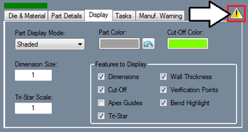
Under the "Display" tab, settings specific to the 3D part display can be adjusted. Select the button below "Cut-Off Color" to change the color that cut-off lengths will be displayed in. This button will display the current color that is in use. To change the size of the Tri-Star or Dimension text, enter values into either of the Tri-Star Scale or Dimension Size field.
Check the box next to Dimensions to have the length measurements and markers displayed in the part display.
Check the box next to Cut-Off to have any cut-off lengths that were entered in the 'Cut-Off Start or End' fields in the Part Details tab shown in the part display.
Check the box next to Apex Guides to to show lines extending from the bend verification points to the part.
Check the box next to Tri-Star to have the XYZ compass/tri-star displayed in the part display.
Check the box next to Wall Thickness to have the thickness of the material shown on the part model when in shaded mode.
Check the box next to the Verification Points to display blue points on the apex of each bend and the start and end of the part.
Check the box next to Bend Highlight to have whichever bend is currently selected (either the cursor is in the design field or selected in the bend list) highlighted on the part model.
Check the box next to Refresh on Keystroke to have the part model constantly updated whenever changed are made to the design.
While any of these options are unchecked, they will not be shown in the current 3D part display area.
Tasks
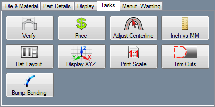
- "Those below with simple functions that are self-explanatory will not have a link to further explanation for how to use the function."
- Select the "Verify"
 button to open the Part Verify window. Using this tool, the dimensions/distances and the angle between two points can be verified.
- Select the "Flat Layout"
 button to open the Flat Layout window. Two flat, unbent models of the same part will be displayed and can be labeled and then printed out.
- Select the "Bump Bending"
 button to add bump bends to a bend on the current part. Bump bending allows bends to be sectioned off into multiple smaller, equal sized bends.
- Select the "Price"
 button to access the Price List window. There, the total costs for a single part, along with a specified amount of the current part can be seen.
Display XYZ/LRA (Excludes XYZ Part Design)
- Depending on which coordinate mode is in use in the Results Table, this button will display either 'Display XYZ' or 'Display LRA'. When one mode is in use, the opposite will be shown on this button. Select this "Display XYZ/LRA"
 button to toggle between them. The results tables for the same part are shown below; LRA table on the left and XYZ table on the right.
Move to Origin (Specific to XYZ Part)
- Select the "Move to Origin"
 button will make it so the starting point of the part will be located at (0, 0, 0). All other points on the point will be adjusted accordingly, so the design will remain the same once the origin is shifted.
Trim Cuts
- If the current part has any cuts applied to the ends (which can be done in the Assembly interface in the Cutting tab), the excess material on the end(s) of the part can be removed by selecting the "Trim Cuts"
 button. The shape of the cut will then be visible. Note: For the cuts to be shown, the Cut-off display option needs to be turned off. This can be done in the Display Tab.
Inch vs MM
- Select the "Inch vs MM"
 button to convert the current units to inches or millimeters. These changes will be shown in the results table, part information/design section, and 3D part display.
- Select the "Apex vs Tangent"
 button to switch the dimension types between apex and tangent for all of the current part's bends.
- Select the "Print Scale"
 button to open the print scale feature. Print Scale allows a full size, to scale, 2D version of single part designs to be printed to scale on multiple sheets.
- Select the "Adjust Centerline"
 button to change how the part measurements are interpreted. In the part designers, parts are assumed to be based on centerline. This tool allows the current part dimensions to be from the inside or outside of the tube instead.
Manuf. Warning
- Under the "Manuf. Warning" tab, manufacturing warnings will be listed if any are available. If there are warnings, a red block will be displayed above the tab. The bend number, description of the problem, and any action that can be taken will be listed for each warning. If an auto-fix is available, double-click on the auto-fix description to execute the auto-fix.
Part Settings Icon
- In the upper right corner of the tabbed section, there will be a
 icon that can be used to access the part settings. For information on the part settings in this menu, see the "Part Settings" page.
Part Display
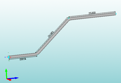
- On the lower right side of the window is the 3D preview of the part. While creating a Custom, Custom 3D, XYZ, or Reverse Design part, the current bend and/or length will be highlighted in red while the bend is either selected or while the bend/start/end coordinate row is selected.
- This preview can be adjusted by zooming, panning, and rotating.
- To zoom, use the scroll wheel on the mouse. Scroll up to zoom out and scroll down to zoom in.
- To pan/move the part preview, click and hold the scroll wheel or both mouse buttons and move the cursor around. The part preview will move with the cursor.
- To rotate, click and hold the right mouse button. Move the cursor around and the part will rotate with the cursor movements.
Results Table
- In the upper right corner of the window, the results table is shown.
- The top section of the results table shows the die, material, cut length, and weight of the part.
- This entire section's color will indicate if any problems exist. If the section is green, it means the part is complete and there are no problems or manufacturing warnings. If section is orange, the part is complete, but some problems or warnings exist. If the section is red, the part is not complete and/or there are warnings or problems with the part design.
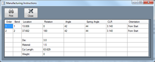
- The results table also holds a chart that lists each bend along with the bend order, location of the bend, amount of rotation needed for the bend, angle of the bend, spring angle value, centerline rotation, bend length, and the orientation of the bend. Double click within this chart to view a full size version in a new window. In this new window, select the "Print" button to print the chart.
