|
|
| (29 intermediate revisions by the same user not shown) |
| Line 1: |
Line 1: |
| | '''[[Main Page|Bend-Tech 7x Wiki]] :: [[Main Menu Bar]] :: [[File]] :: Import''' | | '''[[Main Page|Bend-Tech 7x Wiki]] :: [[Main Menu Bar]] :: [[File]] :: Import''' |
| − | __TOC__
| + | __NOTOC__ |
| | | | |
| − | <h3>[[DXF Import]]</h3>
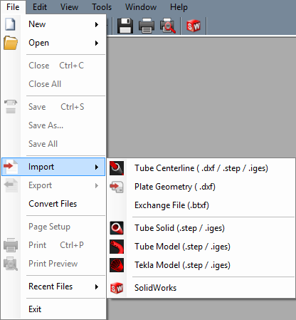
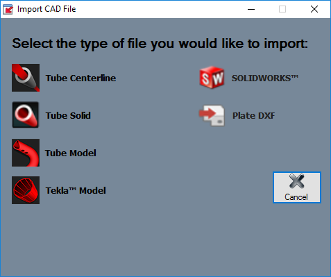
| + | *Files can be imported using the '''File -> Import''' menu or by selecting any of the import options on the [[View#Task Menu|Task Menu]]. |
| | + | '''Importing a Tube Centerline DXF file can be done by following all of the STEP/IGES Import instructions with the exception of the initial button the user presses to start the import.''' |
| | | | |
| − | <h3>[[Exchange File/STEP/IGES/BREP Import]]</h3>
| + | *When using our Industrial or Dragon software, our file importing method will cause the tube to undergo a skinning, or unwrapping process. Read [[Tube Skinning Process]] to gan a better understanding of this. |
| | | | |
| − | <h3>[[SolidWorks]]</h3>
| |
| | | | |
| − | <h2>DXF</h2>
| |
| − | To import a '''DXF''' file, place the cursor over '''Import''' and select '''Data (.dxf)''' in the list. DXF files can also be imported from the [[Task Menu]] by selecting the '''3D DXF''' option under Import File. Choose which file to import in the Import DXF File window. Click 'Open' to open it into an Import Part window.
| |
| | | | |
| − | [[File:import_dxf.png|450px]]
| |
| | | | |
| − | <h3>Die and Material</h3>
| + | [[File:file_import_new1.png|left]] |
| − | In the top left corner, a material and die can be selected. The material selection will be shown in the 3D display of the imported part when the 'Preview Part' button is clicked.
| |
| | | | |
| − | '''To select a material''', click the drop down menu below 'Select Material:' and choose a material from the list. Once a material is selected, the diameter, wall thickness, and weight of the selected material will be shown to the right. To view the [[Tube/Pipe Library]], click the '''Library''' button next to the material selection. A material must be selected before a 3D shaded model of the part can be shown in the part display frame.
| + | [[File:New_CAD_Import_Menu1.png]] |
| | | | |
| − | '''To select a die''', click the drop down menu below 'Select Die:' and choose a die from the list. Once a die is selected, the CLR, calibrated CLR, and bend location offset of the selected die will be shown to the right. Directly below the Select Die drop down menu, the original CLR of the imported part will be shown after 'Detected CLR:'. To view the [[Die Library]], click the '''Library''' button next to the die selection. | + | {| style="text-align: left; width="100%;" |
| | + | |- style="height: 80px;" |
| | + | |[[File:Imp_dxf2.png|link=Tube Centerline Import]] '''[[Tube Centerline Import]]''' || [[File:Imp_step_only1.png|link=STEP/IGES Import]] '''[[STEP/IGES Import]]''' || [[File:Imp_solidworks2.png|link=SolidWorks]] '''[[SolidWorks]]''' |
| | + | |- style="height: 80px;" |
| | + | |} |
| | | | |
| − | | + | {| style="text-align: left; width="100%;" |
| − | | + | |- style="height: 80px;" |
| − | <h3>Define</h3>
| + | |[[File:Tube_Model_Import1.png|link=Industrial Guide]] '''[[Industrial Guide]]''' || [[File:Tekla_Import_Icon1.png|40px|link=Tekla Import Guide]] '''[[Tekla Import Guide]]''' || [[File:Plate_DXF_Import1.png]] '''[[Plate DXF Import]]''' |
| − | [[File:import_dxf_2.png|350px]]
| + | |- style="height: 80px;" |
| − | | + | |} |
| − | *'''Start:''' To manually define the part, click the '''Start''' button [[File:start.png]] and click on the section lines along the part to define it. The sections of the part will turn red as they are being defined.
| |
| − | | |
| − | *'''Auto Track:''' To automatically track and define the shape of the part, click the '''Auto Track''' button. [[File:auto_track.png]] This option will only be available after 'Start' and at least one point on the part shape has been selected.
| |
| − | | |
| − | *'''Flip Arc:''' To reverse the direction of an arc, click the '''Flip Arc''' button. [[File:flip_arc.png]] This will completely change the direction and angle of the arc/bend.
| |
| − | | |
| − | *'''Generate Part:''' When the part is fully defined, either by manually selecting sections or by using the Auto Track function, click the '''Generate Part''' button to bring the bend information into the Part Details chart. Once the part is successfully defined, use the '''Transfer''' menu [[File:transfer.png]] to send the part design to a part interface, nesting project, assembly, etc.
| |
| − | | |
| − | | |
| − | | |
| − | <h3>Verify</h3>
| |
| − | Under the Verify tab, the selected feature's attributes will be shown. Click on a feature to select it. If the selected feature is a line, the length, start and end points will be shown. If the selected feature is an arc, the radius, angle, center, start, and end locations will be shown.
| |
| − | | |
| − | [[File:import_dxf_3.png|350px]]
| |
| − | | |
| − | | |
| − | | |
| − | <h3>Settings</h3>
| |
| − | | |
| − | '''Die References'''
| |
| − | [[File:import_dxf_4.png|right|300px]] | |
| − | Die references can be set up by clicking the '''Die''' button [[File:]] below 'Import References'. This will open the Die References window. The purpose of die references is to automatically assign a die to any bends in a part that have the same material and import radius as the reference. For example, if an imported part is brought into the import interface and is assigned a material that matches the material reference (Under Die and Material in the top right corner) and has the same import radius as the die reference, once 'Generate Part' is clicked, the die reference die will be automatically chosen as the die in the Part Details chart. On the left side of the die references window, there is a list of die references. To view information about a die reference, select it by clicking its name in the list. The fields to the right will display the selected die reference's details. To add a new die reference, click the 'New' button at the bottom of the window. Enter the die reference's name in the 'Name:' field, select a die from the Die drop down menu, select a material from the 'Material' drop down menu, enter an import radius, and select which units to use. Click the 'Apply' button to add it to the list. To delete a die reference, select the die reference from the list and click the 'Delete' button. Click 'Close' to close the Die References window.
| |
| − | | |
| − | | |
| − | | |
| − | | |
| − | | |
| − | | |
| − | '''Material References'''
| |
| − | [[File:import_dxf_5.png|right|300px]]
| |
| − | Material references can be set up by clicking the '''Material''' button [[File:material_ref.png]] below 'Import References'. This will open the Material References window. The purpose of a material reference is to automatically select a material for a part if it has the same import diameter of the material reference. For example, if an imported part has a 2 inch diameter and a material reference's assigned import diameter is 2 inches, the material reference material will be automatically selected (Under Die and Material in the top right corner) once the part is brought into the import interface. A list of all material references will be shown on the left side of the window. To view information about a material reference, select it by clicking its name in the list. The fields to the right will display the selected material reference's details. To add a new material reference, click the 'New' button at the bottom of the window. Enter the material reference's name in the 'Name:' field, select a material from the Material drop down menu, enter a import diameter in the 'Import Diameter' field, and select which units to use. Click the 'Apply' button to add it to the list. To delete a material reference, select the material reference from the list and click the 'Delete' button. Click 'Close' to close the Material References window.
| |
| − | | |
| − | | |
| − | | |
| − | | |
| − | | |
| − | | |
| − | <h3>Part Details</h3>
| |
| − | [[File:import_dxf_1.png|right]] | |
| − | In the top right corner, the part details chart is shown. Once the part has been defined properly and the 'Generate Part' button has been clicked, each bend will be listed with the radius, and a column where each die must be chosen. To select a die for each bend, click on either the die or open space that is currently listed in the Die column. Once clicked, a drop down menu will appear. Click the drop down menu and select a die. To delete a bend, select any of the cells in the bend's row and click the 'Delete Bend' button. If there is only one bend, it cannot be deleted. The part needs at least one bend. After the part has been properly defined and generated, check the '''Show Part''' option to generate the part in the chosen material.
| |
| − | | |
| − | | |
| − | | |
| − | | |
| − | | |
| − | | |
| − | | |
| − | | |
| − | | |
| − | | |
| − | <h2>Exchange File/STEP/IGES/BREP</h2>
| |
| − | | |
| − | | |
| − | | |
| − | | |
| − | <h2>SolidWorks</h2>
| |
| − | To import a part from SolidWorks™, both Bend-Tech and SolidWorks™ need to be open and running.
| |
| − | | |
| − | First, the '''3D Sketch''' or '''Sweep''' of the SolidWorks part needs to be selected in the SolidWorks software.
| |
| − | | |
| − | [[File:import_sw_1.png]] [[File:import_sw_2.png|600px]]
| |
| − | | |
| − | | |
| − | | |
| − | | |
| − | | |
| − | Next, go up to the '''menu bar''' at the top of the SolidWorks window, place the cursor over the '''Bend-Tech option''', and click '''Process Bend Info'''.
| |
| − | | |
| − | [[File:import_sw_3.png]]
| |
| − | | |
| − | | |
| − | | |
| − | | |
| − | The '''Send To Bend-Tech''' panel will now be shown on the left side of the window. Select the 3D Sketch or Sweep by clicking on it. Once the correct feature is selected, click on the green arrow icon.
| |
| − | | |
| − | [[File:import_sw_4.png]] [[File:import_sw_5.png]]
| |

