Difference between revisions of "Header Design"
(Created page with "'''Bend-Tech 7x Wiki :: Header Design''' __NOTOC__ right|500px The header design interface allows header tubes to be created and edited. ...") |
|||
| Line 37: | Line 37: | ||
{|style="text-align:center; width:100%; font-size: 170%;" | {|style="text-align:center; width:100%; font-size: 170%;" | ||
|- | |- | ||
| − | |'''[[Header - Main|Main]]''' || '''[[Header - Points|Points]]''' || '''[[Header - Edit|Edit]]''' || '''[[Header - Dimensions|Dimensions]]''' || '''[[Header - Explode|Explode]]''' || '''[[Header - Details|Details]]''' | + | |'''[[Header - Main|Main]]''' || '''[[Header - Points|Points]]''' || '''[[Header - Edit|Edit]]''' || '''[[Header - Steps|Steps]]''' || '''[[Header - Dimensions|Dimensions]]''' || '''[[Header - Explode|Explode]]''' || '''[[Header - Details|Details]]''' |
|} | |} | ||
Revision as of 14:33, 11 June 2014
Bend-Tech 7x Wiki :: Header Design
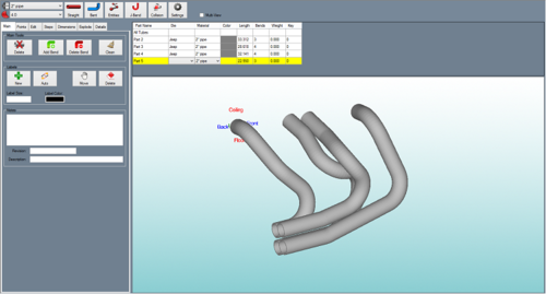
The header design interface allows header tubes to be created and edited.
To open a new header design:
1.) Go to the File menu, select New -> Header.
2.) Click the New Assembly icon ![]() at the top of the window.
at the top of the window.
...OR
3.) Select the Header Design option from the Task Menu that appears when the software starts up, when all designs are closed, or through the view menu.
Tabs
A majority of the header design features and functions are located in the tabbed section on the right hand side of the window. To find information about how to use these features, see the links below.
| Main | Points | Edit | Steps | Dimensions | Explode | Details |
Header Menu
h3>Material</h3>
![]() In the material menu, the material for the parts in the header can be selected. To select a material, click the drop down menu and choose a material from the list. This material can be changed for each individual part later, this is just the material that is initially applied to new parts. Tube/pipe materials are defined in the Tube/Pipe Library.
In the material menu, the material for the parts in the header can be selected. To select a material, click the drop down menu and choose a material from the list. This material can be changed for each individual part later, this is just the material that is initially applied to new parts. Tube/pipe materials are defined in the Tube/Pipe Library.
Die
![]() In the die menu, the die used to bend the parts in the header design can be selected. To select a die, click the drop down menu and choose a die from the list. This can be changed for each individual part later, this is just the die that is initially applied to new parts. Dies are defined in the Die Library.
In the die menu, the die used to bend the parts in the header design can be selected. To select a die, click the drop down menu and choose a die from the list. This can be changed for each individual part later, this is just the die that is initially applied to new parts. Dies are defined in the Die Library.
Straight
To create a straight tube between two PickPoints, click the Straight button  and click any two PickPoints or Auto points (points that are automatically generated along parts, such as mid points, apex point, or start and end of bend points ) in the display window.
Bent
To create a new bent part, click the Bent button.  To design the part, you must select the start point and the location of each bend, and the end point of the part.
Entities
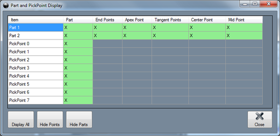
The Entities tool controls which parts and points are displayed in the header. Click the Entities button  to open up this menu. Each row will represent straight part, bent part, and PickPoint. To hide a certain feature, click in the green box to remove the X. To have all features shown, click Display All button.
 ![]() To hide all PickPoints, click the Hide Points
To hide all PickPoints, click the Hide Points ![]() button. To hide all parts, click the Hide Parts button.
button. To hide all parts, click the Hide Parts button. ![]()


