Header Design
Bend-Tech 7x Wiki :: Header Design
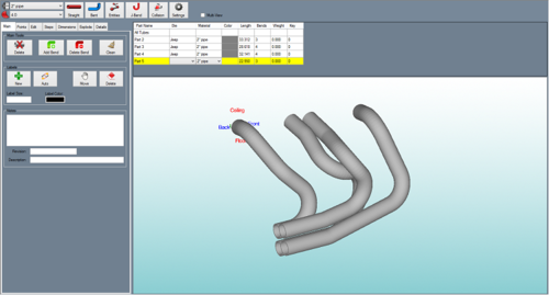
The header design interface allows header tubes to be created and edited.
To open a new header design:
1.) Go to the File menu, select New -> Header.
2.) Click the New Assembly icon ![]() at the top of the window.
at the top of the window.
...OR
3.) Select the Header Design option from the Task Menu that appears when the software starts up, when all designs are closed, or through the view menu.
Icon Toolbar
At the top of the frame just below the main menu bar, there is a series of icons.
Click the New Part icon ![]() to open the create new menu. This menu will allow you to choose a new part designer interface and begin a new part design.
to open the create new menu. This menu will allow you to choose a new part designer interface and begin a new part design.
Click the New Assembly icon ![]() to open a new assembly design. See the Assembly page for further information on creating an assembly.
to open a new assembly design. See the Assembly page for further information on creating an assembly.
Click the New Plate icon ![]() to open a new plate design. See the Plate page for further information on designing a plate.
to open a new plate design. See the Plate page for further information on designing a plate.
Click the New Header icon ![]() to open a new header design.
to open a new header design.
Click the Open icon ![]() to open a part, assembly, plate, or header file.
to open a part, assembly, plate, or header file.
Click the Save icon ![]() to save the current active window's progress. If the current window is a new and hasn't been saved previously, the part will need to be given a name and location. Click 'Save' in the Save window to save.
to save the current active window's progress. If the current window is a new and hasn't been saved previously, the part will need to be given a name and location. Click 'Save' in the Save window to save.
Click the Print icon ![]() to print out an image of the current view of the header design.
to print out an image of the current view of the header design.
Click the Print Preview icon ![]() to view a preview of the header design image print out.
to view a preview of the header design image print out.
Click the Solidworks icon ![]() to import a part file from Solidworks that has been sent to Bend-Tech.
to import a part file from Solidworks that has been sent to Bend-Tech.
Click the Display menu ![]() to alternate between a line or shaded part model.
to alternate between a line or shaded part model.
Click the Refresh icon ![]() to refresh the part display.
to refresh the part display.
Click the Home button ![]() to reset the 3D part display to its original default view.
to reset the 3D part display to its original default view.
Click the Zoom button ![]() to zoom all the way in on the current view of the 3D part display and fit it to the display frame.
to zoom all the way in on the current view of the 3D part display and fit it to the display frame.
Click on the Transfer menu ![]() to send
to send
Click on the Projections icon ![]() to view the current design from a specified plane (top, bottom, left, right, front, or back) or from a certain angle.
to view the current design from a specified plane (top, bottom, left, right, front, or back) or from a certain angle.
Header Chart
In the header chart shown above the part display, each tube will be listed along with its die, material, color, length, number of bends, weight, and key number.
To change the die of an individual part, click in the die field and select a die from the menu.
To change the material for a part, click in the material field and select a material from the menu.
To change the color of a part, click in the color field and select a color from the menu.
Tabs
A majority of the header design features and functions are located in the tabbed section on the right hand side of the window. To find information about how to use these features, see the links below.
| Main | Points | Edit | Steps | Dimensions | Explode | Details |
Header Menu
Material
![]() In the material menu, the material for the parts in the header can be selected. To select a material, click the drop down menu and choose a material from the list. This material can be changed for each individual part later, this is just the material that is initially applied to new parts. Tube/pipe materials are defined in the Tube/Pipe Library.
In the material menu, the material for the parts in the header can be selected. To select a material, click the drop down menu and choose a material from the list. This material can be changed for each individual part later, this is just the material that is initially applied to new parts. Tube/pipe materials are defined in the Tube/Pipe Library.
Die
![]() In the die menu, the die used to bend the parts in the header design can be selected. To select a die, click the drop down menu and choose a die from the list. This can be changed for each individual part later, this is just the die that is initially applied to new parts. Dies are defined in the Die Library.
In the die menu, the die used to bend the parts in the header design can be selected. To select a die, click the drop down menu and choose a die from the list. This can be changed for each individual part later, this is just the die that is initially applied to new parts. Dies are defined in the Die Library.
Straight
To create a straight tube between two PickPoints, click the Straight button  and click any two PickPoints or Auto points (points that are automatically generated along parts, such as mid points, apex point, or start and end of bend points ) in the display window.
Bent
To create a new bent part, click the Bent button.  To design the part, you must select the start point and the location of each bend, and the end point of the part.
Entities
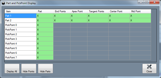
The Entities tool controls which parts and points are displayed in the header. Click the Entities button  to open up this menu. Each row will represent straight part, bent part, and PickPoint. To hide a certain feature, click in the green box to remove the X. To have all features shown, click Display All button.
 ![]() To hide all PickPoints, click the Hide Points
To hide all PickPoints, click the Hide Points ![]() button. To hide all parts, click the Hide Parts button.
button. To hide all parts, click the Hide Parts button. ![]()
J-Bend
Click the J-Bend button to open up the J-Bend menu.
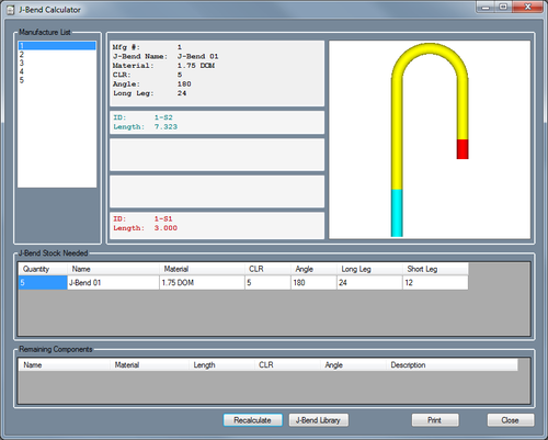
In this window, the cut instructions to create the header from J-bends is shown. For this to work properly, the J-Bend Library must have J-Bends made of the same material(s) and CLR(s) as the header tubes and need to have the correct lengths.
Below Manufacture List a list of each J-bend needed is shown. To view which sections that J-bend will be used for, click on a number in the list to select it. The selected J-bend's details, cut instructions, and a preview of the bend will be shown to the right. The color of the text indicates which section of the J-bend it's referring to. For example, if the text is red, that information is for the section of the J-bend that is highlighted in red in the preview panel.
Below J-Bend Stock Needed, a list of all the J-bends used for the header is shown. The amount used, the name of the J-bend, the material of the J-bend, the CLR, angle, and short and long leg lengths are given here.
Below Remaining Components, any sections of the header that could not be created are shown. The name of the section, it's material, length, CLR, angle, and a description of why it could not be created are shown.
Click the Recalculate button to reassess the cut instructions to attempt to get successful cut instructions after adding new J-bends to the J-Bend Library.
Click the J-Bend Library to open the J-Bend Library. Once opened, J-bends can be edited or added if necessary.
Click Print to print out a customized Job Cut Instructions sheet.
Collision
Click the Collision button to check the header design for collisions/intersections between header tubes.
Settings
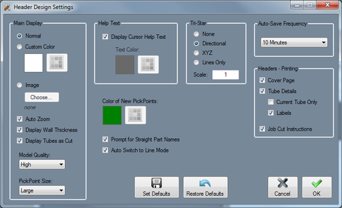
Click the Settings button  to access the header settings menu. These settings are used to control the display and general options within the current header design.
Main Display
The main display settings control the part display and part model appears in the header interface. The background of the main display can be shown.
- Background: Select the Normal option for the part display background to be shown with the normal blue to white gradient. Select the Custom Color option to choose a custom solid color. Select the Image option to select an image file to display as the background.
- Auto Zoom: Check this option to automatically zoom all the way in on the current view of the 3D part display and fit it to the display frame.
- Display Wall Thickness: Check this option to have the thickness of the material shown on the part model when in shaded mode.
- Display Tubes as Cut: Check this option to have the profiles of any cuts on the tubes represented on the part model.
- Model Quality: To adjust the graphic quality of the part model, select an option from this menu. Parts can be shown in high, medium, and low quality.
- PickPoint Size: To adjust the size of all the pickpoints shown in the display frame, select an option from this menu.
Help Text: Check the box next to Display Cursor Help Text to toggle the help text on and off in header design. This help text will help guide certain processes within header. The color of this text can be adjusted using the Text Color option.
Tri Star
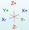
These options will control how the tri-star will appear in the current header design. The tri-star can be Directional (labeled with ceiling/floor, front/back, left/right), XYZ (labeled with X, Y, and Z), Lines Only, or None (not shown at all). The default scale value can also be defined here, which will control how large the tri-star will appear.
Color of New PickPoints: The default color of new PickPoints can be adjusted here. Click the color button and select a color from the menu to choose a new PickPoint color.
Prompt for Straight Part Names: While this option is checked, every time a new straight part is added to the header design, a window will prompt for a name to be given to this part instead of defaulting to "Straight 1" for example.
Auto Switch to Line Mode: Check this option to have the display mode automatically switched to line mode whenever new points or parts are being added/edited in the current header design.
Auto-Save Frequency: The time interval between the automatic saves can be adjusted using this menu.
Headers - Printing
- Cover Page: Check this option to include a cover sheet with the setup sheet for the header design.
- Tube Details: Check this option to have details about each tube (die, material, length, etc.) included on the setup sheet for the header design.
- Current Tube Only:
- Labels: Check this option to have the labels (added in the Main tab) included on the header model on the setup sheet.
- Job Cut Instructions:
Set Defaults: Click the Set Defaults button ![]() to use these settings as the defaults for future header designs.
to use these settings as the defaults for future header designs.
Restore Defaults: Click the Restore Defaults button ![]() to reset all the settings to the default selections.
to reset all the settings to the default selections.
Multi-View
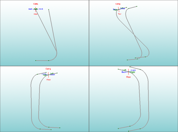
Check the box next to Multi-View to split the header design part display into 4 sections that view the part from different directions. See image below for an example.
